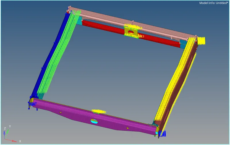
Week 9-Creation of 1D Connectors Challenge
OBJECTIVE
- To mesh the given Frame Assembly using a target element size of 5 units and validate the mesh as per the quality criteria provided.
- To create connectors and attach the various parts of the assembly.
PROCEDURE
- The Frame Assembly is imported using the Import Model option.
- The various components of the assembly are manually cleaned up before meshing to ensure better mesh quality.
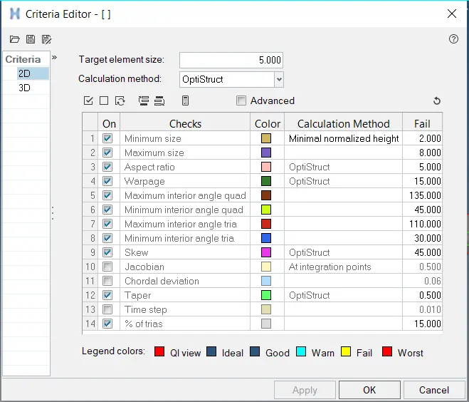
- Before the meshing process, the quality criteria has to be defined as shown below.
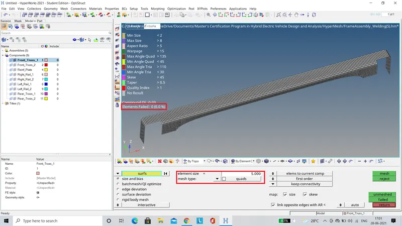
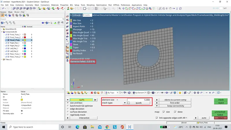
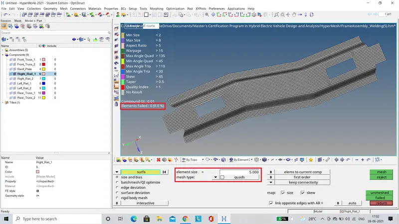
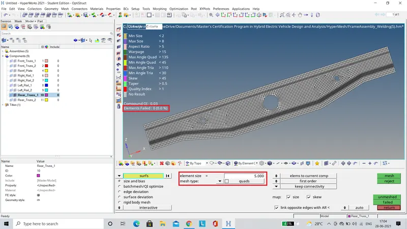
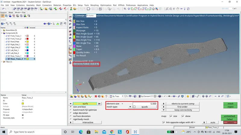
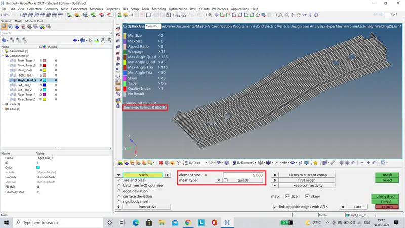
- The meshing is done seperately on each component of the assembly.The target element size is set to 5 units and the mesh type is set to quads.After the meshing is done, the mesh quality has to be validated and the failing elements should be rectified.
- After the meshing process, the various parts of the assembly are attached together using the respective connectors.
Right Rail 2 & Front Truss 1
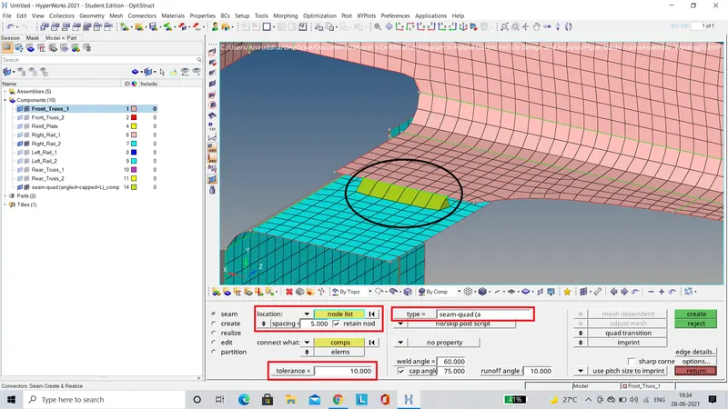
The two components are connected using the Seam tool present in the 1D connectors panel.To begin with, the type of seam has to be selected which in our case is 'seam-quad(angled+capped+L)'.The spacing defined should be equal to the element size we have used to mesh the components.The search tolerance should be defined such that the entities within the tolerance range are taken into account for link detection and the final realization.Finally, the node list is selected to define the position of the seam and the components between which the seam has to be created are selected.After the seam is created, the mesh on the components gets disrupted and has to be rectified.
Left Rail 2 & Front Truss 1
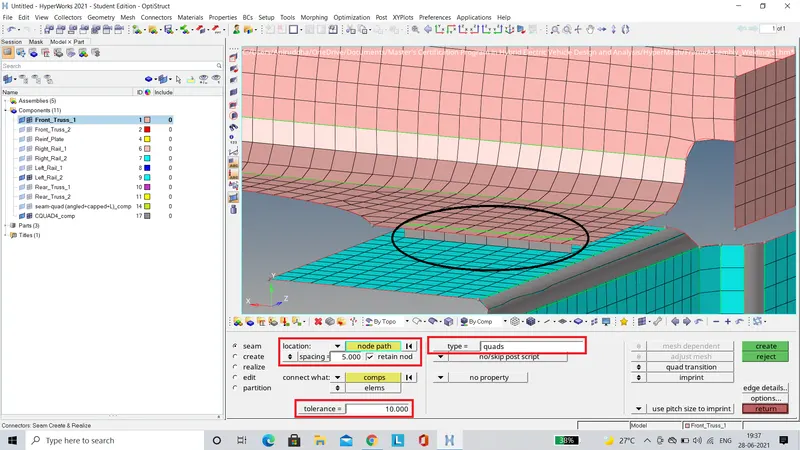
These two components are also connected using the Seam tool present in the 1D connectors panel.The only diffference in this case is that, the seam type is set to 'quads'.Rest of the parameters are defined similar to the previous case.
Front Truss 2, Front Truss 1 & Right Rail 1
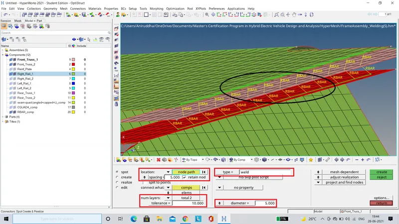
These three components are connected using the Spot tool present in the 1D connectors panel.In this case, the type is set to 'weld'. The number of layers is set to 2 and the diameter is set to 5 units.Rest of the parameters are defined similar to the previous case.In this case since there are three components present, two spot welds have to be created, one between each component.
Front Truss 2, Front Truss 1 & Left Rail 1
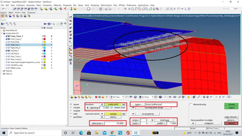
These three components are connected using the Seam tool present in the 1D connectors panel.The type is set to 'hexa(adhesive)'.The number of strips is set to 2 and coats to 3.Strips are the number of hexa elements required along the width, whereas coats are the number of hexa elements required along the thickness.The width of the adhesive is set to 1 unit.Finally, the node path is selected to position the adhesive and the components to be connected are selected.
Rear Truss 2 & Right Rail 2
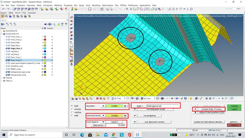
The two components are connected using the Bolt tool present in the 1D connectors panel.The type is set to 'bolt(general)'. Since there are no holes present in the FEA, we have to select the 'create hole, if none' option as shown above.Finally, the nodes are placed to define the position of the bolts and the components which have to connected are selected.
Rear Truss 2 & Left Rail 2
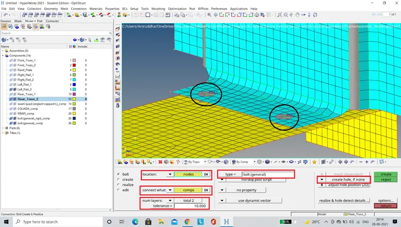
These two components are connected in a manner similar to the previous case.
Right Rail 1 and Right Rail 2
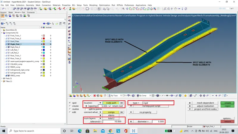
The two components are connected using the Spot tool present in the 1D connectors panel.The type is set to 'rigid'.Rest of the parameters are set similarly to the previous case where a Spot Weld was created.
Left Rail 1 & Left Rail 2
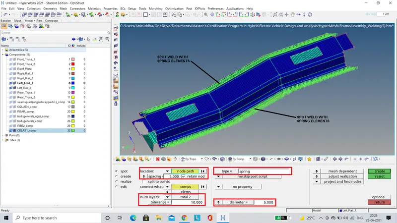
These two components are connected in a manner similar to the previous case, but the only difference being is that the spot type is set to 'spring'.
Front Truss 1, Front Truss 2 & Reinf Plate
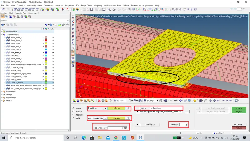
These three components are connected using the Area tool present in the 1D connectors panel.The type is set to 'adhesives'. The number of coats is set to 2 and the tolerance is defined as per the distance between the components.Finally, the elements on the Reinf Plate are selected to position the adhesives and then all the components are selected to create the connection.
FINAL MODEL IMAGE