Week 9-Challenge
Aim: Attaching various parts of the given model by creating different connectors available in the hypermesh
Tools used:
- Auto mesh in the 2D panel
- Smooth in the 2D panel
- connectors in the 1D panel
Procedure:
- Firstly, import the component into the hypermesh window and select the profile as "Optistruct"
- Change the geometry colour mode from "Auto" mode to "by topo" mode to look at the geometry properly
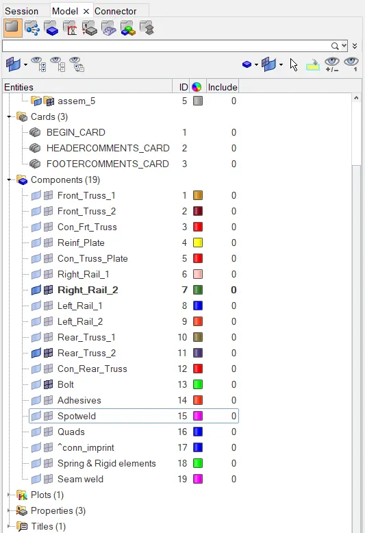
ALL THE COMPONENTS ARE GIVEN AND CREATED ARE SHOWN IN THE TAB AREA
- After importing the component go for auto mesh command in the 2d panel to generate the mesh
- After entering into the auto mesh, individually mesh the surfaces one after the other
- Select the rear truss2 surface and enter the target element size and change the element type to Mixed elements and click on the mesh button
- The mesh is generated on the rear truss2 surface and remove all the rotating quad elements by remeshing it again
- After completing the meshing process, hide the geometry and start working on the mesh
- Select the right rail2 surface which is to be connected to the rear truss2 surface and start meshing on the other component
- After completing the meshing process on the right rail2 component try to connect them with suitable connectors like a bolt, spot weld etc are available in the hypermesh
- After completing the meshing on the right rail2 component go for 1D panel and click on the connectors tool
- After entering into the connectors tool click on the bolt option
- Before creating the connectors open the connector browser in the tab area where all the connections are seen between the components
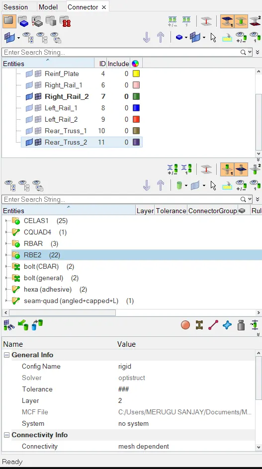
ALL THE CONNECTORS CAN BE SEEN IN THE CONNECTOR BROWSER IN THE TAB
- After entering into the bolt connectors hide the geometry of the components in the tab area which have to be connected
- Create a new component as Bolt in the tab area which represents a bolt connection
- Select the nodes on the mesh on the rear truss 2 and select the type of bolt for example like bolt(CBAR) select the two components rear truss 2 and right rail 2 in connecting what section and with the help of a dropdown button on right side change the option to create hole, if none option and select with no property option and click on create button the bolt connection will be created on the selected nodes
- After connecting the two surfaces the mesh on the surfaces will get distorted so try to remesh the area again in order to obtain a smooth mesh flow
- Similarly, connect the other components with suitable connectors in the same by meshing them and connecting them
- Save the model by using save as in the file menu after creating connectors and attaching it to various parts given in the model within the given criteria
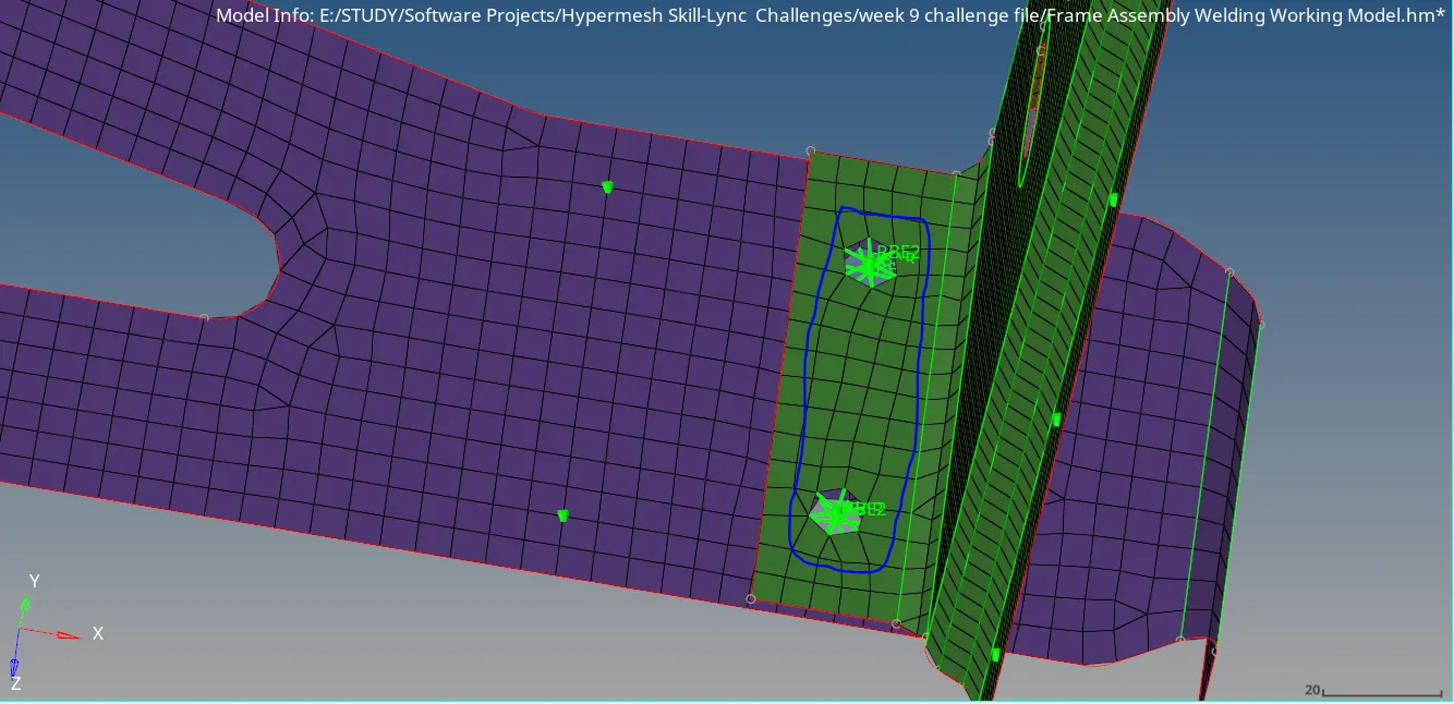
REAR TRUSS2 & RIGHT RAIL2 WITH BOLT CONNECTION
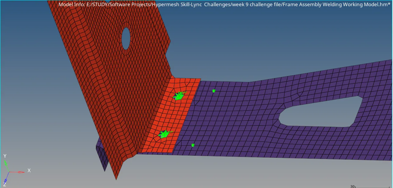
REAR TRUSS2 & LEFT RAIL 2 WITH BOLT CONNECTION
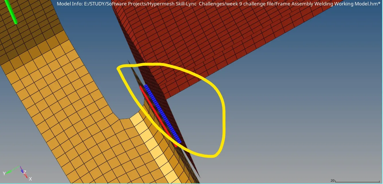
FRONT TRUSS1 & LEFT RAIL2 WITH QUAD CONNECTION
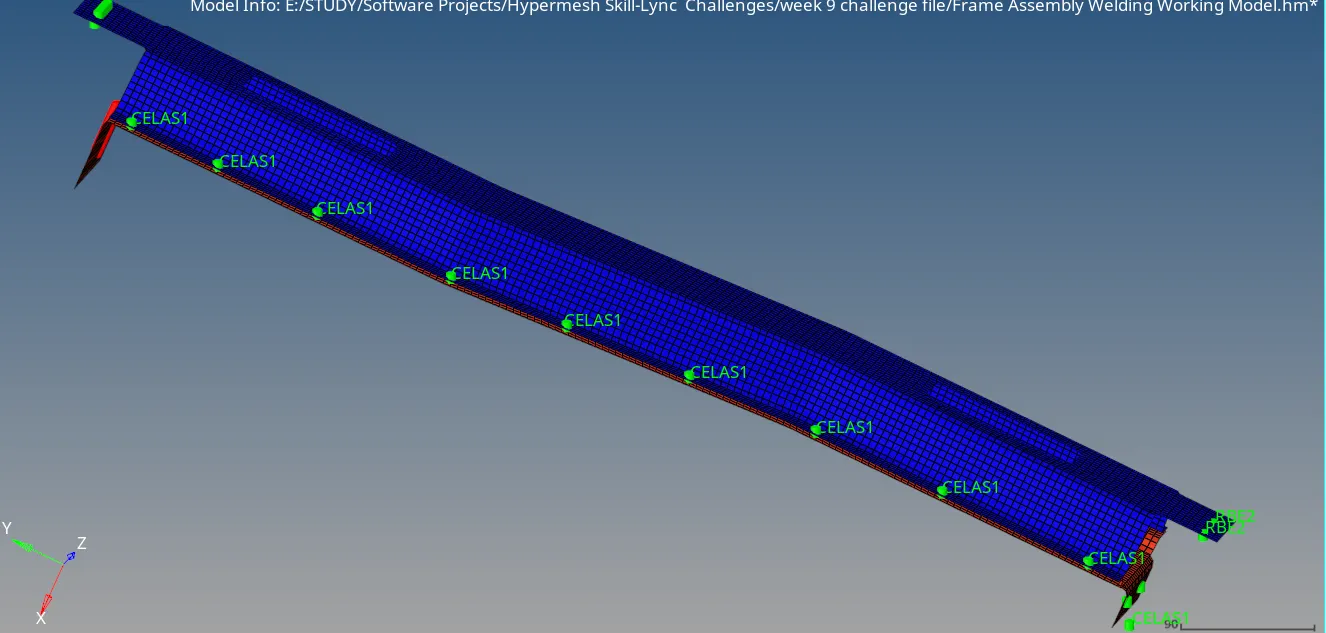
LEFT RAIL & LEFT RAIL 2 WITH SPOT WELD CONNECTION OF SPRING ELEMENTS SEEN AS CELAS1
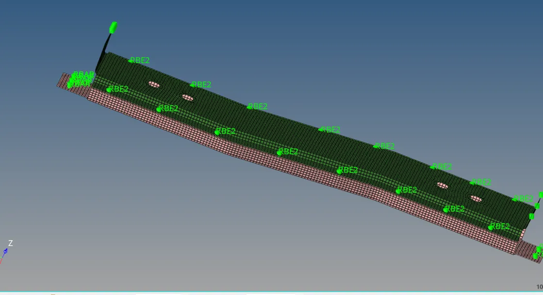
RIGHT RAIL1 & RIGHT RAIL2 WITH SPOT WELD OF RIGID ELEMENTS SEEN AS RBE2
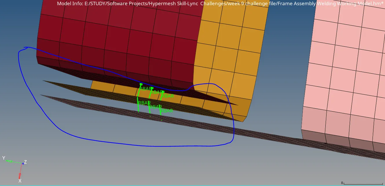
FRONT TRUSS1, FRONT TRUSS2 & RIGHT RAIL1 WITH SPOT WELD CONNECTION SEEN AS RBAR
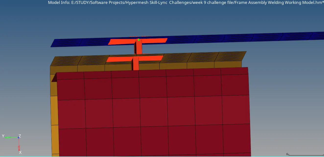
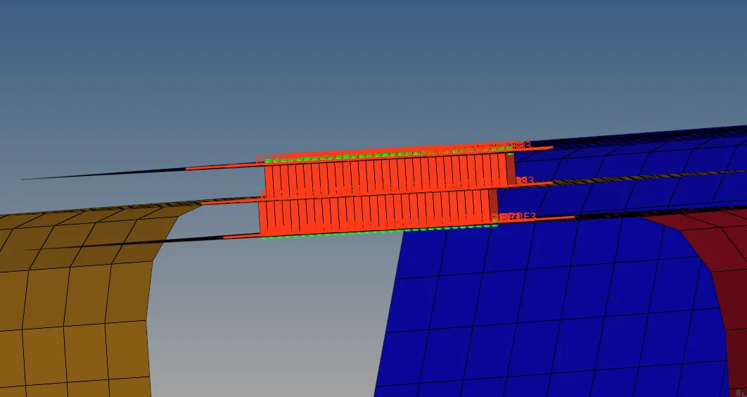
FRONT TRUSS2, FRONT TRUSS1 & LEFT RAIL 1 WITH ADHESIVES(HEXA) CONNECTION
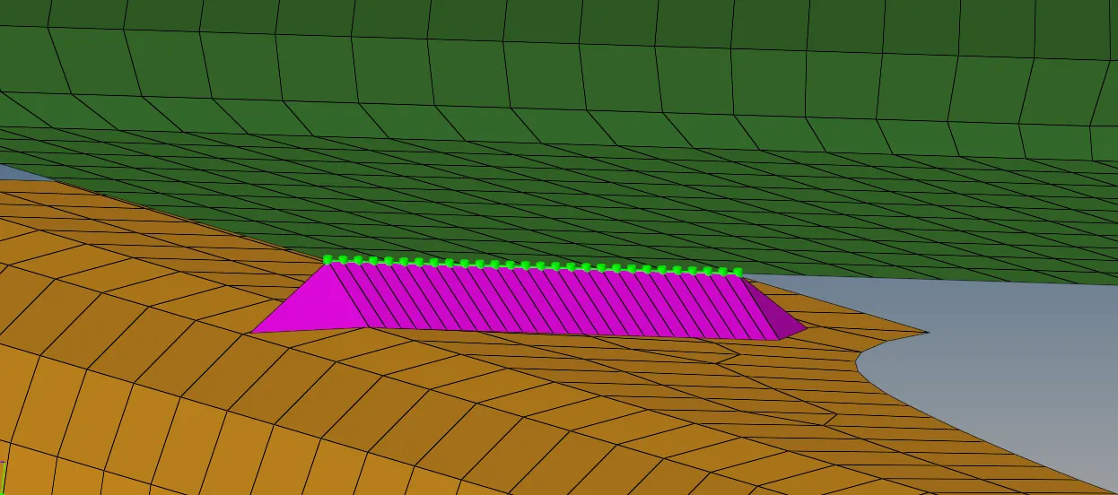
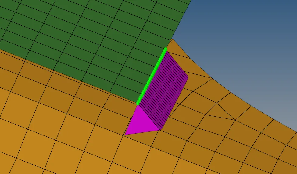
RIGHT RAIL2 & FRONT TRUSS1 WITH SEAM-QUAD CONNECTION
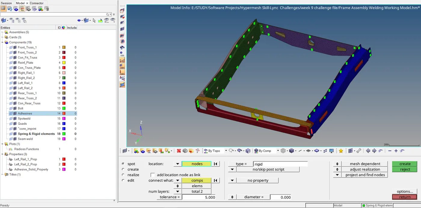
ALL THE PARTS WITH THE CONNECTORS SHOWN IN THE WINDOW AND IN THE TAB
Conclusion: The connectors are created and attached to various parts of the given model with the given criteria