Assignment 1
Objective:
Carry out the geometry cleanup operation on the given 3 files.
- Practice
- Clip Repair
- Mounting Bracket
There should not be any free edges, convert all of them into a refined geometry.
- Clean the geometry.
- Extract midsurface.
- Clean midsurface geometry.
- Ignore holes less than dia 5mm.
- Create a 2D mesh with target length 5mm, min 3.5mm max 7mm.
- And assign proper thickness, by creating a generic property to the given 3 files.
Tools Used:
- The edge-edit tool in the geometry panel
- The surfaces tool in the geometry panel
- The surface-edit tool in the geometry panel
- The delete tool in the tool panel
- The midsurface tool in the geometry panel
- The auto mesh tool in the 2D panel
- The quality index tool in the 2D panel
- The check-elements tool in the tool panel
Part-1 Model
Procedure:
- Open the hypermesh software and select the profile as "RADIOSS".
- Import the first model i.e. "Part-1" model from the given 3 files by using the "Import model" option present in the file menu at the top.
- After importing the model delete if any of the solids present in the model by using the "delete" option present in the tool panel.
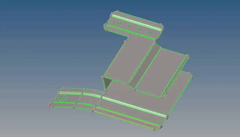
PART-1 PARENT GEOMETRY AFTER IMPORTING
- After deleting the solids in the model, perform the geometry cleanup manually by using all the available tools present in the hypermesh tool panel.
- check out if any free edges (appear in red colour) present in the model if there are any free edges present by using the "toggle edge" option in the Quick-Edit tool present in the geometry panel.
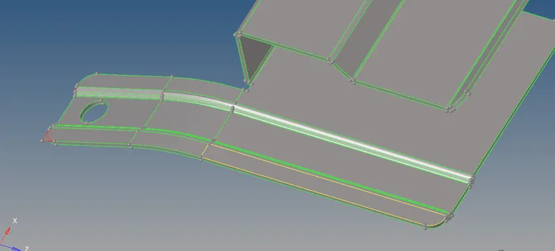
PART-1 GEOMETRY WITH FREE EDGES
- Toggle all the free edges present in the model by using the "toggle edge" option in the quick-edit tool.
- Also, check if any dual surfaces( appear in the yellow colour) present in the model if there are any dual surfaces delete them by using delete option.
- After deleting the surfaces, trim all the unnecessary surfaces by using "surface-edit" tool in the geometry panel.
- By using "Trim with lines" option in the surface-edit tool trim all the unnecessary surfaces and after trimming delete the trimmed surfaces.
- After deleting all the unnecessary surfaces, go for "Surfaces" tool in the geometry panel to create surfaces wherever needed.
- After entering the surfaces tool, select the option "Ruled". Change the option from nodes to lines in the toolbar.
- Click the first line list and select the first line and then click the next line list and select the second line on the surface which is opposite to the first line and then click on the create button a surface will be created.
- This process is applicable only for the linear surfaces not for the nonlinear surfaces.
- After performing all the necessary geometry cleanup on the given model, extract the midsurface from the given model.
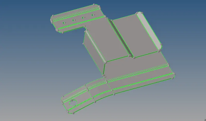
PART-1 PARENT GEOMETRY AFTER CLEANUP
- Click on the "midsurface" tool in the geometry panel, after entering into the toolbar select the auto extraction option, select "auto midsurface" option and in the extraction options select the option "Offset+Planes+Sweeps".
- Select the whole surface by using the 'displayed' option and click on the extract option.
- The midsurface will be extracted and check if any geometry cleanup is needed.
- After extracting the midsurface, perform the meshing operation on the given model.
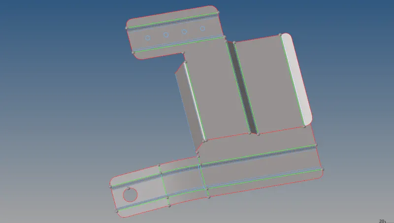
PART-1 MIDDLE SURFACE AFTER CLEANUP
- Click on the 2D panel and select the "Automesh" tool in the panel.
- After entering the Automesh tool panel, select the element type and change the element type from 'Quads' to 'Mixed' option.
- Enter the target element size as 5mm, after changing all the parameters select the surface and click on mesh button to create the mesh
- The mesh will be generated on the midsurface check for any rotating quads present on the mesh if there any rotating quads present in the mesh try to remove them by remeshing them again and again.
- After removing all the rotating quads, go for the "Check-elements" tool in the tool panel.
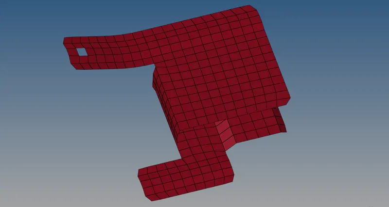
PART-1 MIDDLE SURFACE MESH
- After entering into the check elements tool panel, enter the values given for the minimum size and maximum size.
- Check for the failed elements for min size and max size if there any failed elements present in the mesh try to clear the failed elements by using the quality index tool in the 2D panel.
- Click on the 2D panel and select the "Quality Index" tool.
- In the Quality index tool, there are several options like node optimize, element optimize, place node etc.
- By using all the available options in the quality index, clear all the failed elements for min size and max size.
- After clearing all the failed elements, create a property with proper thickness and assign it to the meshed surface.
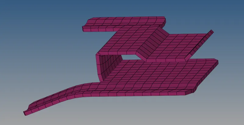
PART-1 MIDDLE SURFACE WITH MESH AND THICKNESS ASSIGNED
- Try to save the model by using the save model option present in the file menu at the top-left of the window save the model in .hm format.
Part-2 Model
Procedure:
- Open the hypermesh software and select the profile as "RADIOSS".
- Import the first model i.e. "Part-2" model from the given 3 files by using the "Import model" option present in the file menu at the top.
- After importing the model delete if any of the solids present in the model by using the "delete" option present in the tool panel.
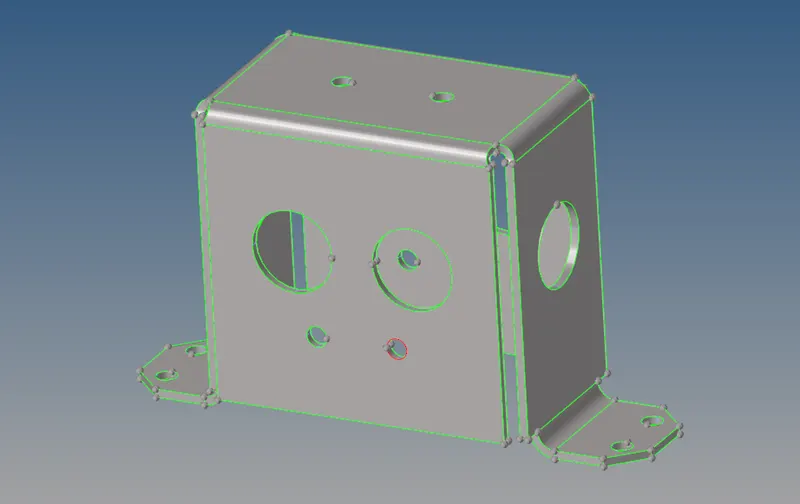
PART-2 MODEL PARENT GEOMETRY AFTER IMPORTING
- After deleting the solids in the model, perform the geometry cleanup manually by using all the available tools present in the hypermesh tool panel.
- check out if any free edges (appear in red colour) present in the model if there are any free edges present by using the "toggle edge" option in the Quick-Edit tool present in the geometry panel.
- Toggle all the free edges present in the model by using the "toggle edge" option in the quick-edit tool.
- Also, check if any dual surfaces( appear in the yellow colour) present in the model if there are any dual surfaces delete them by using delete option.
- After deleting the surfaces, trim all the unnecessary surfaces by using "surface-edit" tool in the geometry panel.
- By using "Trim with lines" option in the surface-edit tool trim all the unnecessary surfaces and after trimming delete the trimmed surfaces.
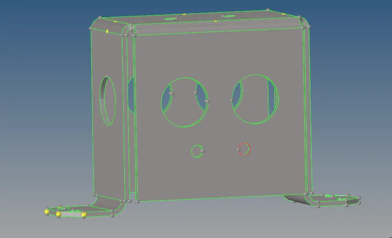
PART-2 PARENT GEOMETRY CLEANUP
- After performing all the necessary geometry cleanup on the given model, extract the midsurface from the given model.
- Click on the "midsurface" tool in the geometry panel, after entering into the toolbar select the auto extraction option, select "auto midsurface" option and in the extraction options select the option "Offset+Planes+Sweeps".
- Select the whole surface by using the 'displayed' option and click on the extract option.
- The midsurface will be extracted and check if any geometry cleanup is needed.
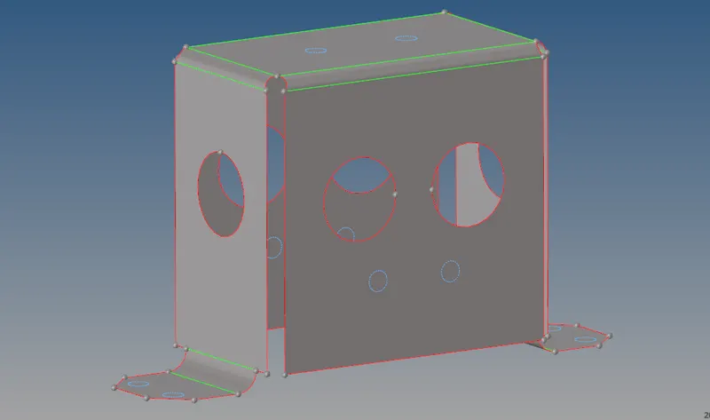
PART-2 MIDDLE SURFACE GEOMETRY CLEANUP
- After extracting the midsurface, perform the meshing operation on the given model.
- Click on the 2D panel and select the "Automesh" tool in the panel.
- After entering the Automesh tool panel, select the element type and change the element type from 'Quads' to 'Mixed' option.
- Enter the target element size as 5mm, after changing all the parameters select the surface and click on mesh button to create the mesh
- The mesh will be generated on the midsurface check for any rotating quads present on the mesh if there any rotating quads present in the mesh try to remove them by remeshing them again and again.
- After removing all the rotating quads, go for the "Check-elements" tool in the tool panel.
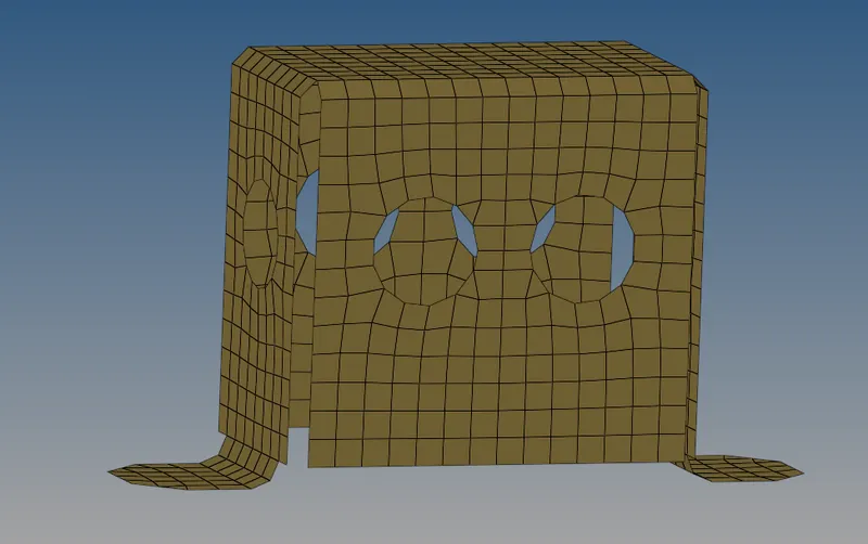
PART-2 MIDDLE SURFACE WITH 2D MESH
- After entering into the check elements tool panel, enter the values given for the minimum size and maximum size.
- Check for the failed elements for min size and max size if there any failed elements present in the mesh try to clear the failed elements by using the quality index tool in the 2D panel.
- Click on the 2D panel and select the "Quality Index" tool.
- In the Quality index tool, there are several options like node optimize, element optimize, place node etc.
- By using all the available options in the quality index, clear all the failed elements for min size and max size.
- After clearing all the failed elements, create a property with proper thickness and assign it to the meshed surface.
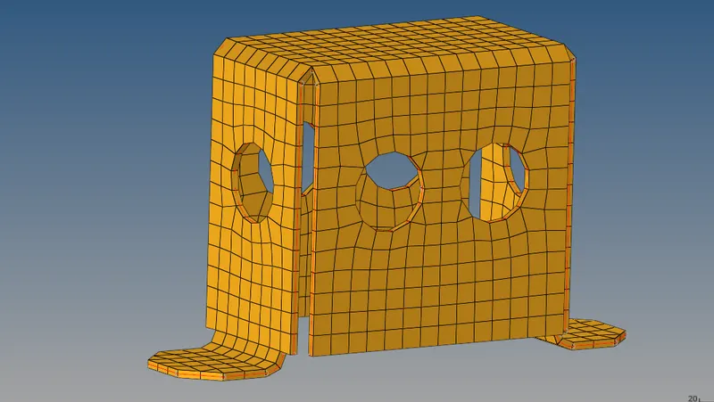
PART-2 MIDDLE SURFACE WITH MESH AND THICKNESS ASSIGNED
- Try to save the model by using the save model option present in the file menu at the top-left of the window save the model in .hm format.
Part-3 Model
Procedure:
- Open the hypermesh software and select the profile as "RADIOSS".
- Import the first model i.e. "Part-3" model from the given 3 files by using the "Import model" option present in the file menu at the top.
- After importing the model delete if any of the solids present in the model by using the "delete" option present in the tool panel.
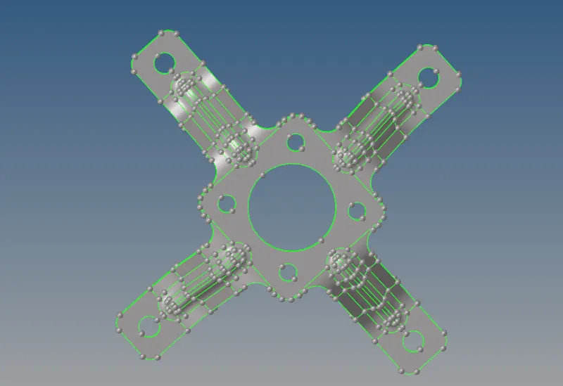
PART-3 MODEL PARENT GEOMETRY AFTER IMPORTING
- After deleting the solids in the model, perform the geometry cleanup manually by using all the available tools present in the hypermesh tool panel.
- check out if any free edges (appear in red colour) present in the model if there are any free edges present by using the "toggle edge" option in the Quick-Edit tool present in the geometry panel.
- Toggle all the free edges present in the model by using the "toggle edge" option in the quick-edit tool.
- Also, check if any dual surfaces( appear in the yellow colour) present in the model if there are any dual surfaces delete them by using delete option.
- After deleting the surfaces, trim all the unnecessary surfaces by using "surface-edit" tool in the geometry panel.
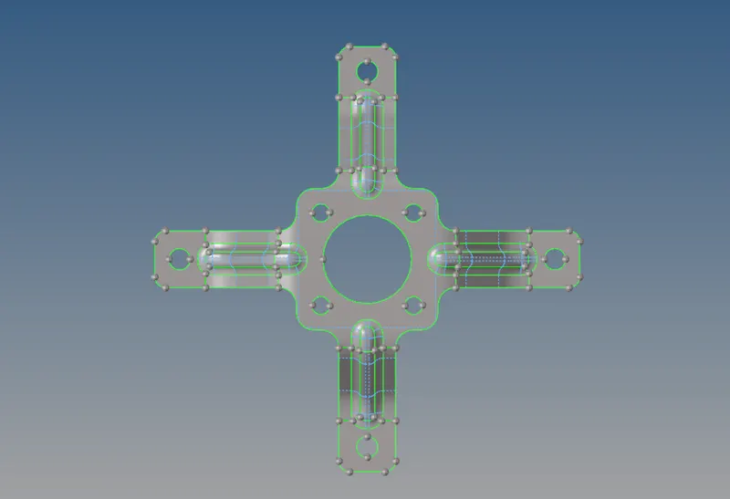
PART-3 PARENT GEOMETRY CLEANUP
- After performing all the necessary geometry cleanup on the given model, extract the midsurface from the given model.
- Click on the "midsurface" tool in the geometry panel, after entering into the toolbar select the auto extraction option, select "auto midsurface" option and in the extraction options select the option "Offset+Planes+Sweeps".
- Select the whole surface by using the 'displayed' option and click on the extract option.
- The midsurface will be extracted and check if any geometry cleanup is needed.
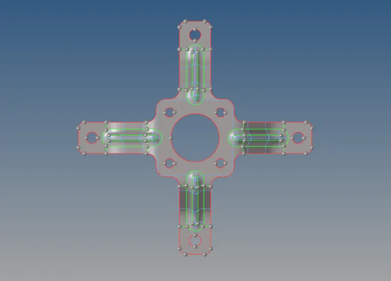
PART-3 MIDDLE SURFACE AFTER GEOMETRY CLEANUP
- After extracting the midsurface, perform the meshing operation on the given model.
- Click on the 2D panel and select the "Automesh" tool in the panel.
- After entering the Automesh tool panel, select the element type and change the element type from 'Quads' to 'Mixed' option.
- Enter the target element size as 5mm, after changing all the parameters select the surface and click on mesh button to create the mesh
- The mesh will be generated on the midsurface check for any rotating quads present on the mesh if there any rotating quads present in the mesh try to remove them by remeshing them again and again.
- After removing all the rotating quads, go for the "Check-elements" tool in the tool panel.
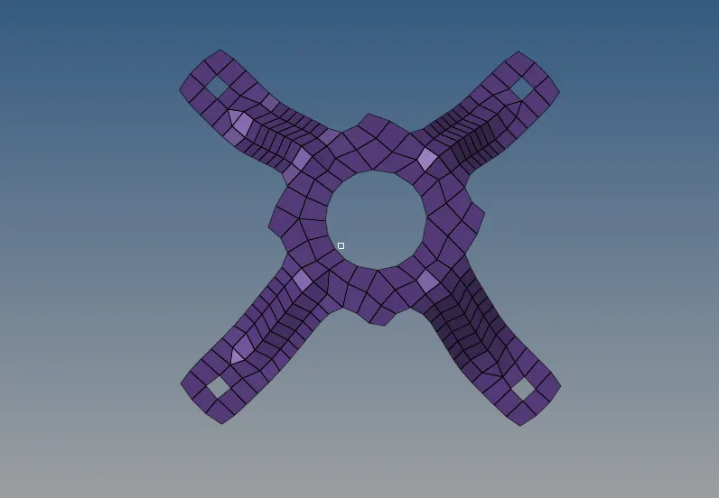
PART-3 MIDDLE SURFACE WITH 2D MESH
- After entering into the check elements tool panel, enter the values given for the minimum size and maximum size.
- Check for the failed elements for min size and max size if there any failed elements present in the mesh try to clear the failed elements by using the quality index tool in the 2D panel.
- Click on the 2D panel and select the "Quality Index" tool.
- In the Quality index tool, there are several options like node optimize, element optimize, place node etc.
- By using all the available options in the quality index, clear all the failed elements for min size and max size.
- After clearing all the failed elements, create a property with proper thickness and assign it to the meshed surface.
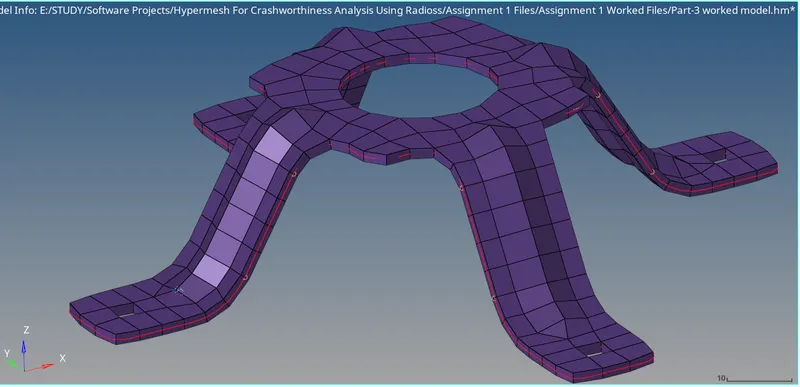
PART-3 MIDDLE SURFACE WITH MESH AND ASSIGNED THICKNESS
- Try to save the model by using the save model option present in the file menu at the top-left of the window save the model in .hm format.
Conclusion:
The geometry cleanup is performed, the midsurface has been extracted, the 2d mesh is generated on the extracted midsurface, the quality is checked for the given parameters and property is assigned with proper thickness. This sequence of process is carried out on all the given 3 models individually.