Assignment 3
Objectives:
Comparison of results with base simulation and improved shell element properties
1.Using the crash beam file from the previous assignment, change the run time to 55 ms.
2. Change the number of animation steps during simulation to a minimum of 25 and maximum of 60.
3. Run the base simulation without any modification to element properties.
4. At the end of the simulation, do the energy error and mass error checks and determine whether results would be acceptable.
5. If acceptable, Plot rigid wall forces, internal energy, hourglass energy, contact energy, the total energy of the simulations.
6. Change all the shell elements properties to recommended properties, save this as separate, rad files and run the simulation.
7. Follow steps 5 and 6.
8. Create a brief report comparing all the results from steps 5 and 6 for both simulations.
9. Comment whether there is any change in the results and why there is any change in the result.
Procedure:
Case - 1
- Using the crash beam file from the previous assignment, change the run time to 55 ms.
- Change the number of animation steps during simulation to a minimum of 25 and maximum of 60.
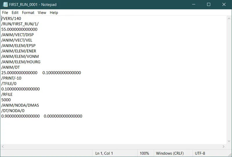
ENGINE FILE MODIFIED AND CHANGED THE RUNTIME TO 55 ms
- Run the Base simulation without any modification in the property cards.
- Import the Starter file into the hypermesh window through the Import Solver Deck option in the File menu.
- Import the Element Formulation Shell_0000.rad file and check the properties of the imported file and make sure there are no values selected in the property card.
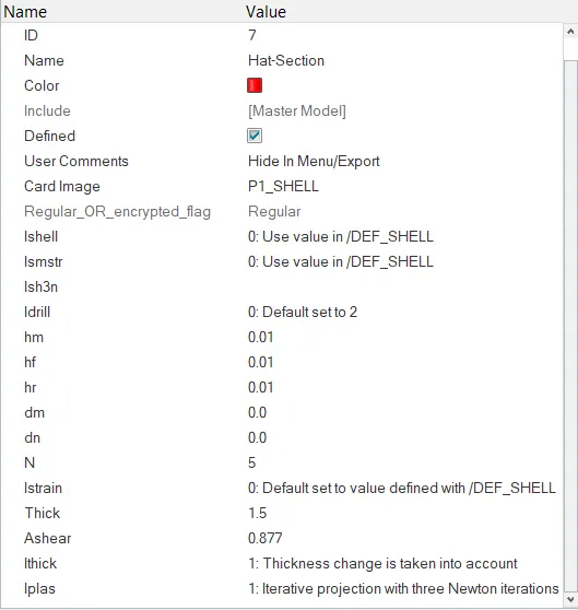
DEFAULT VALUES ARE SET FOR THE BASE SIMULATION IN THE HAT SECTION PROPERTY CARD
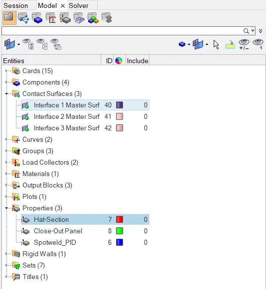
MODEL TAB
- Run the base simulation, to run the simulation click on the Analysis panel in that select Radioss tool. Upon entering the toolbar click on the save as and select a folder to save the file.
- Click on the options button at the bottom enter the value as -nt 4 in the box and click on the Radioss button the analysis gets started once clicking on the Radioss button.
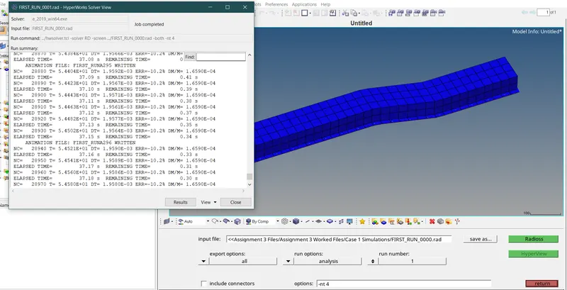
THE RESULTS DISPLAYED ON THE SEPERATE WINDOW
- Split the window into 2 separate layouts to open the HyperView window.
- Select the 2nd window layout and then select the HyperView to look at the base simulation.
- In the load model, select the .h3d file from the .out file to run the simulation and check on the load results option present behind the load model option.
- Once after loading the .h3d file click on the Apply button. The simulation starts to run on the HyperView window once you click on the play button on the toolbar.
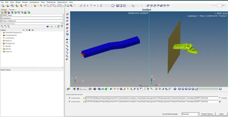
THE 2 SPLIT LAYOUTS SHOWING THE HYPERMESH AND HYPERVIEW WINDOWS
- The way elements have been deformed shows the Hourglass energy (Zero Energy Deformations) errors.
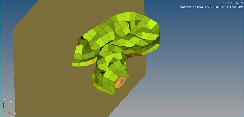
HOURGLASS ERRORS OCCUR AS THE ELEMENTS ARE NOT CONTROLLED AT THE END
- If possible, plot the graph for the Hourglass energy, Contact energy, Total energy, Internal energy and Rigid wall forces by opening the HyperGraph window separately.
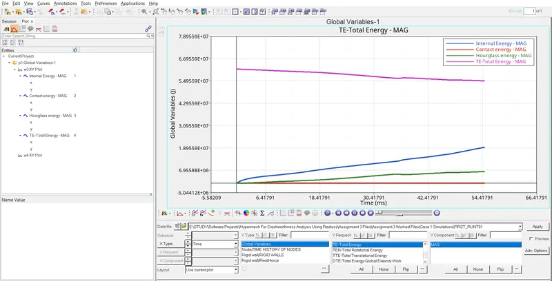
IN THE GRAPH YOU CAN SEE THE HOURGLASS ENERGY IS NOT CONTROLLED AS THE LINE RISES FROM ZERO ONCE AFTER THE START OF THE SIMULATION
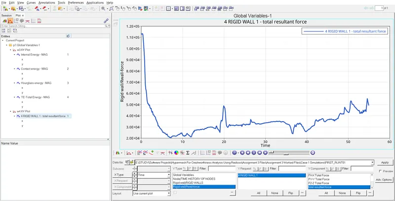
RIGID WALL FORCES PLOTTED ON THE GRAPH
- Check for the energy errors and mass errors at the end of the simulation which is in the .out file for the 55ms runtime.
- Open the ELEMENT FORMULATION SHELL_0001.out file and check for the errors, the maximum energy error is -10.3% and the mass error is 0.1659E-03.
Procedure:
Case - 2
- Open the hypermesh software and select the profile as "Radioss".
- Import the Element Formulation Shell_0000.rad file again into the hypermesh window.
- Before running the simulation change the material properties according to the given Recommended properties.
Recommended properties:
| Parameters | Comment | |
|
Ishell =24 |
QEPH 4 nodes shells are the best combination of cost and accuracy. | |
|
Ismstr=2 |
Full geometric nonlinearities (default)with possible small strain formulation activation in RADIOSS Engine. | |
|
Ish3n=2 |
Standard 3 noded shell (C0)with modification for large rotation(default) |
|
| N=5 | The number of integration points set to 5 for accuracy bending. | |
|
Ithick=1 |
Thickness change is taken into account for accuracy. |
|
|
Iplas=1 |
Iterative plasticity for good accuracy. |
- After changing the property values to the recommended values, try to simulate the model.
MODEL TAB
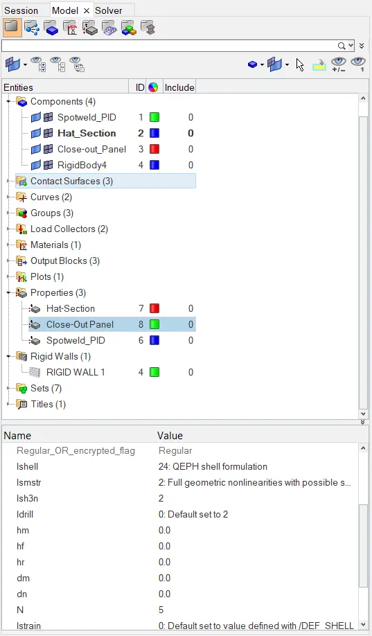
THE VALUES CHANGED IN THE PROPERTY CARD TO THE RECOMMENDED PROPERTIES
- Simulate entering the recommended values in the property cards, to run the simulation click on the Analysis panel in that select Radioss tool. Upon entering the toolbar click on the save as and select a folder to save the file.
- Click on the options button at the bottom enter the value as -nt 4 in the box and click on the Radioss button the analysis gets started once clicking on the Radioss button.
THE RESULTS DISPLAYED ON THE SEPERATE WINDOW
- Split the window into 2 separate layouts to open the HyperView window.
- Select the 2nd window layout and then select the HyperView to look at the base simulation.
- In the load model, select the .h3d file from the .out file to run the simulation and check on the load results option present behind the load model option.
- Once after loading the .h3d file click on the Apply button. The simulation starts to run on the HyperView window once you click on the play button on the toolbar.
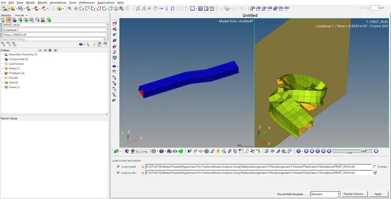
THE 2 SPLIT LAYOUTS SHOWING THE HYPERMESH AND HYPERVIEW WINDOWS
- The Hourglass energy is controlled to some extent because of the recommended values we have entered in the property cards.
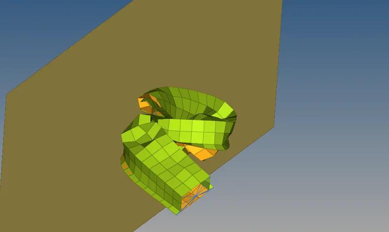
THE HOURGLASS ENERGY HAS BEEN CONTROLLED BECAUSE THE ELEMENTS HAVE NOT BEEN DEFORMED TOO MUCH COMPARED WITH THE CASE 1 IN THE HYPERVIEW WINDOW
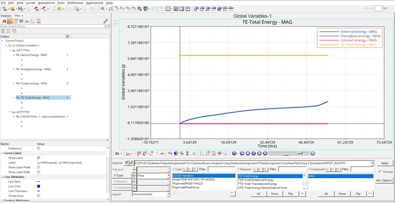
- If possible, plot the graph by selecting the HyperGraph and open it in a separate window. Plot the graph for the Hourglass energy, Contact energy, Total energy, Internal energy and Rigid wall forces on the graph in order to view errors in a detailed manner.
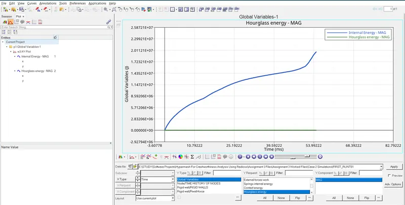
THE HOURGLASS ENERGY IS STABLE THROUGHOUT THE SIMULATION SEEN IN THE GRAPH (GREEN COLOUR)
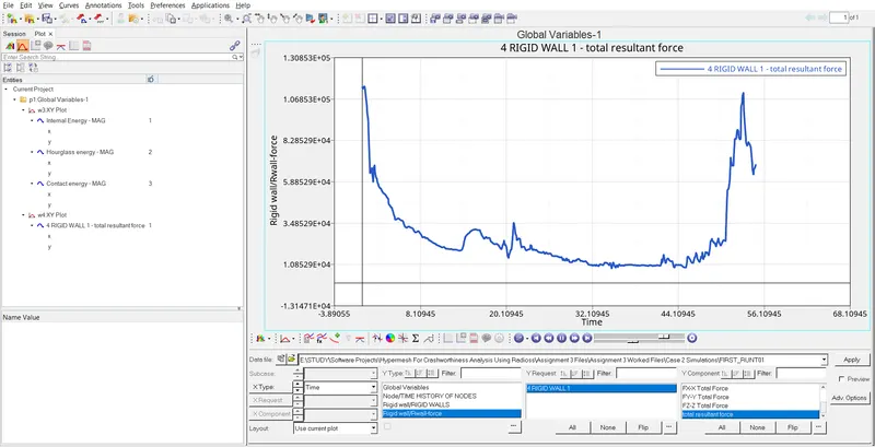
RIGID WALL FORCES ALSO PLOTTED ON THE GRAPH
- Check for the energy errors and mass errors at the end of the simulation which is in the Element Formulation Shell_0000.out file for the 55ms runtime.
- Open the ELEMENT FORMULATION SHELL_0001.out file and check for the errors, the maximum energy error is -0.1% and the mass error is 0.1659E-03. constant throughout the two cases.
Comparison of Case 1 & Case 2 Simulations:
- The simulation run on case 1 is not good as the elements distort at various locations as hourglass errors take place.
- The simulation run on case 2 is decent as most of the hourglass errors has been controlled and it almost zero in case 2 because of the recommended properties.
Comparison of case 1 and case 2 simulations on the HyperGraph
- The Energy error is -10.3 for case 1 but it is only 0.1% in case 2. The value -10.3 is not acceptable.
- The mass error is constant for case 1 and case 2. the value is 0.1659E-03.
Conclusion:
- The engine file has been modified as the run time changed to 55ms.
- The component is subjected to crash simulation with and without the recommended properties.
- The energy error and the mass error has been checked in case 1 and case 2 simulations.
- The HyperGraph has been plotted for the Various energy parameters and also for the rigid wall force which is mentioned in the question.