Assignment 2
Objective:
1. Check the material properties of the rail component and calculate the speed of sound in steel rail=______
2. The length of the rail is about 1000 mm. calculate the time takes for a shock wave to travel from one end of the rail to the other.
3.Time for sound to travel length of rail=______
4.Edit the engine file so that the stress wave can be monitored, moving from one end of the rail to the other during an impact - this will require a termination time equal to the time it takes for the sound to travel the length of the rail(set on/RUN card)
5.Set the frequency of animation output to a time that will give 20 animation steps (/ANIM/DT)
6.Change /print -10.
7.3d meshing tetra mesh and hex mesh
- Repeat class examples and, maintain quality.
- Target tet size=5mm,hex size=10mm,tet collapse=0.15.
Calculations:
- Check the material properties of the rail component and calculate the speed of sound in steel rail = 5188.74mm/ms
C = √(E/ρ)
E = 210000
ρ = 0.0078
C = 5188.74 mm/ms
- The length of the rail is about 1000 mm. calculate the time takes for a shock wave to travel from one end of the rail to the other.
- Time for sound to travel the length of rail = 0.192ms
Length of the rail = l = 1000 mm
Speed of the sound = c = 5188.74 mm/ms
Time is taken for the shock wave to travel the length of the rail = DT
DT = l/c
= 1000/5188.74
= 0.192 ms
- Edit the engine file so that the stress wave can be monitored, moving from one end of the rail to the other during an impact -this will require a termination time equal to the time it takes for the sound to travel the length of the rail (set on/RUN card)
- Set the frequency of animation output to a time that will give 20 animation steps(/ANIM/DT)
- Total time is taken for the sound to travel the length of rail = 0.192/20 = 0.0096 ms
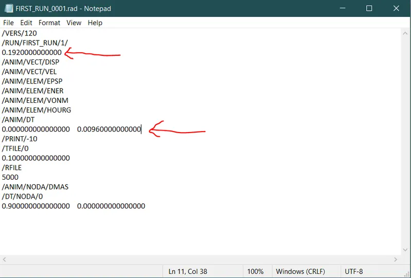
ENGINE FILE MODIFIED WITH CALCULATED VALUES
1D Elements Creation
Procedure:
- Import the 1d elements model into the hypermesh window by using the "Import model" option present at the top left of the window in the file menu.
- After importing the 1d model, the model consists of two plates in which one plate has meshed completely & the other plate hasn't meshed.
- Firstly, create a surface by using the given lines for the plate by using the 'Surfaces' tool in the geometry panel.
- Click on the Geometry panel - Select the 'Surfaces' tool - Select the 'Ruled' option.
- Upon clicking on the Ruled option - click on the first Line list option and select the First-line - click on the second Line list option and select the Second line which is opposite to the first line.
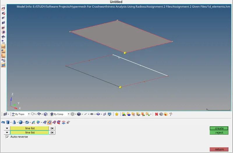
1 & 2 LINE LISTS SELECTED IN RULED COMMAND
- After selecting the 2 lines under 2 line lists click on the create button, a surface will be created.
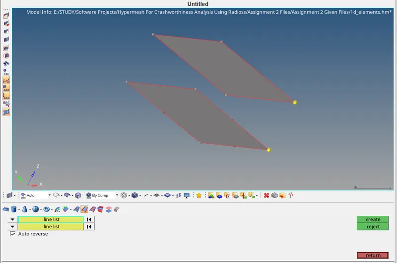
SURFACE CREATED BY USING RULED COMMAND
- After creating the surface try to mesh the two surfaces by using the Automesh tool in the 2D panel.
- Click on the 2D panel select the Automesh tool.
- Upon entering into the Automesh tool, enter the Mesh size as 5mm then change the element type as Mixed elements and check the Align and Size options.
- Select the surface and click on the Mesh button to generate the mesh on the surface. Similarly, perform the same process on the other surface.
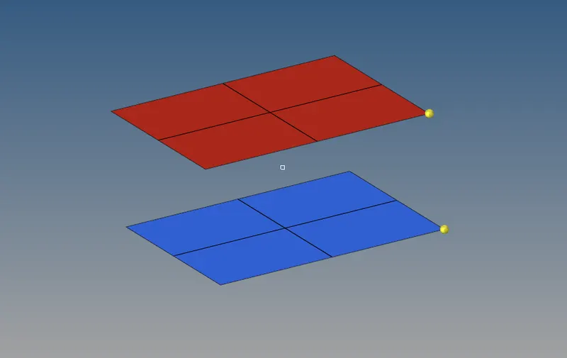
2D MESHING DONE ON THE TWO SURFACES
- Create 1d elements between the two plates, create a 1D beam element between the two surfaces.
- To create a beam, Firstly create a component name it as Beam then click on the 1D panel - select bars - select a node on the element on the first surface as node A then select a node on the element on the second surface as node B.
- In the orientation, change it to the 'Direction' option then select a node on the element as a direction node after selecting the first and second nodes.
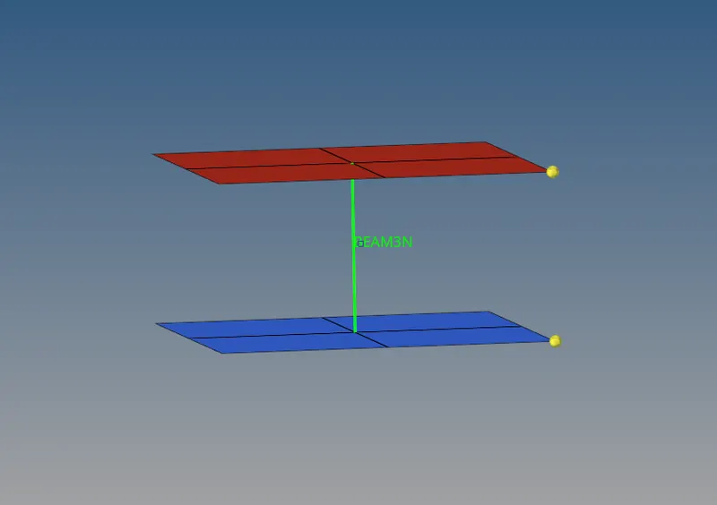
1D BEAM ELEMENT REAPRESENTATION
- After creating a 1D beam element, click on the Hyper beam icon present in the model tab. A new hyper beam window will be opened.
- Right-click in the hyper beam window model tab, select Create - then select standard section - select hypermesh - select the Solid rectangle and enter the values to create the rectangle in the hyper beam window.
- Come back to the hypermesh window, create a property - select the card image as P3 BEAM and in the hyper beam section select the Solid rectangle which has been created in the hyper beam window.
- Assign the Property and Material to the bar component which is created in the tab.
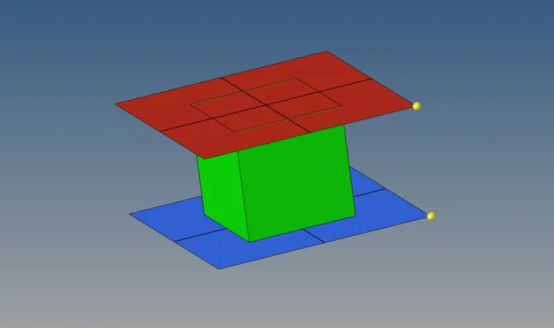
1D BEAM ELEMENT DETAILED REPRESENTATION
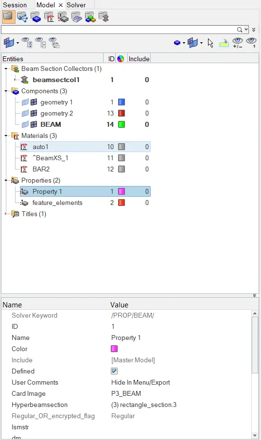
1D ELEMENTS MODEL TAB
- After creating the beam element, save the model by selecting the Save model option in the File menu. Save the model in .hm format.
3D Tetra Mesh On The Housing Model
Procedure:
- Import the Housing model into the hypermesh window.
- After importing the model try to 3D mesh the components. The housing model consists of two components.
- One is the Cover and the second one is Hub.
- Firstly, mesh the cover component and then mesh the hub component.
- To mesh the Cover component, click on the 2D panel, select the 'Automesh' tool.
- Upon entering into the Automesh tool, change the element type as Trias then enter the target element size as 5mm.
- After this, select the entire cover surface then click on the mesh button, the 2D mesh is generated on the cover surface.
- After 2D meshing, click on the 3D panel select the Tetramesh tool to 3D mesh the component.
- Upon entering into the Tetramesh panel, change from comps to elements in the fixed Trias option.
- Select all the 2D elements and check all the options in the panel and click on the mesh button.
- The Tetramesh is generated on the component. After the 3D mesh is generated on the surface of the Cover component, delete the 2D Tria elements by using the delete option in the tool panel.
- Check for the failed elements by using the tet collapse tool. Click on the Tool panel - select the 3-d option in this enter the value for the Tet collapse and check if any of the tetra elements are getting failed.
- If any tetra elements are failing, click on the 3D panel - select the Tetramesh then select the Tetra remesh parameters option.
- Enter the values for Tet collapse and check all the remaining tools in the panel. After entering the values, select the Tetra remesh tool in the panel.
- In the 3D elements option, select all the 3d elements on the surface and click on the remesh button. After generating the mesh again on the surface check for tet collapse in the check elements tool in the tool panel.
- Repeat the same process until the tet collapse becomes zero.
- Similarly, repeat the same process for the Hub component to generate 3D mesh on the component.
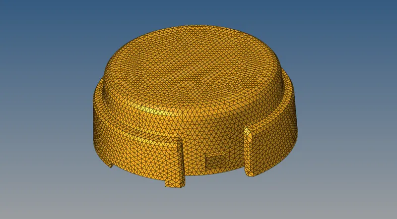
3D TETRAMESH ON THE COVER COMPONENT
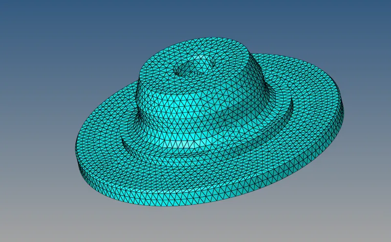
3D TETRAMESH ON THE HUB COMPONENT
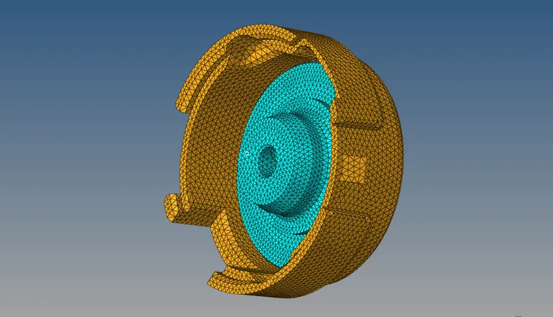
3D TETRAMESH ON THE HOUSING MODEL
- After meshing both the components, save the model in .hm format by Save model option present in the File menu.
3D Hexa Mesh On The Arm Bracket Model
Procedure:
- By using the "Import model" option in the File menu, import the "Arm Bracket" model into the hypermesh window.
- Upon importing the model, try to 3D mesh the components in the model using Hexa elements.
- The Arm Bracket model has 4 components, try to 3D mesh the components with different methods by using different tools.
- Firstly, mesh the Base component, by using the Element offset tool present in the 3D panel.
- Click on the 2D panel, select the 'Automesh' tool and change the element type from Mixed elements to Quads only.
- Enter the Target element size as 10mm, then select the top surface of the base model and click on the mesh. The 2D mesh is generated on the surface.
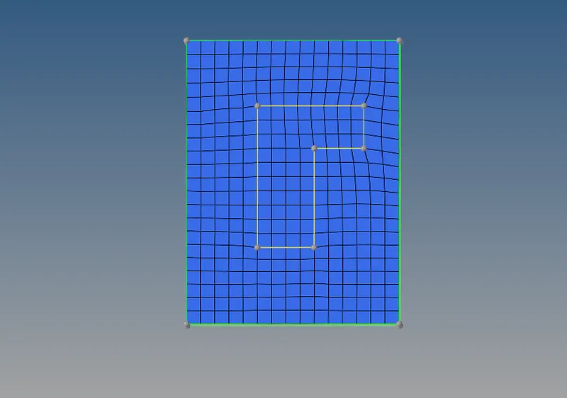
2D MESH WITH QUADS
- After creating the 2D mesh on the model, click on the 3D panel and select the 'Element Offset' tool.
- In the Element Offset toolbar select the option Solid layers, select the 2D elements in the 2D elements to offset option, select the no of layers option and enter the value as 5, select the total thickness and enter the value as 25 in it.
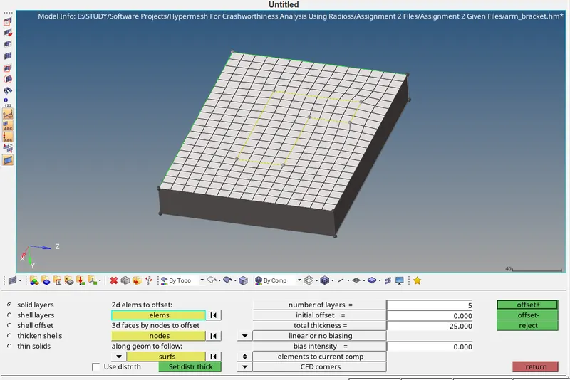
- Select the sides of the base component in the 'along geometry to follow' option and click on the offset + or offset - button. Upon clicking on the offset + button the 3D Hexa mesh is created on the component.
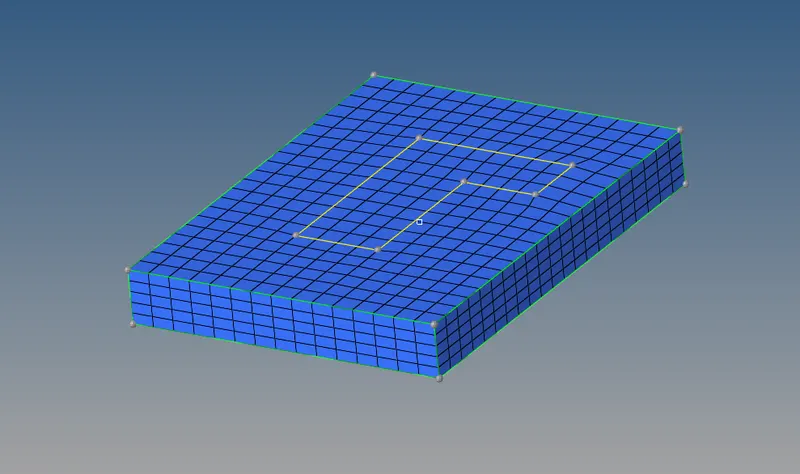
BASE COMPONENT WITH 3D HEXA MESH
- After completing the meshing on the Base component, then mesh the Arm curve component.
- Click on the Geometry panel and select Nodes tool, select the Arc centre option, select any circular line on the arm curve that will create a node.
- Click on the 3D panel, select the Spin option, after entering into the toolbar select the 2D elements on the L-shaped surface on the base.
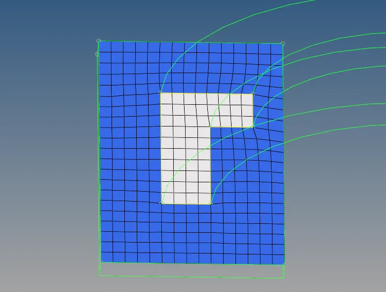
ELEMENTS SELECTED ON THE L-SHAPED AREA
- Select the angle and enter the value like 90 degrees then select the on spin and enter the value as 25 & select the x-axis and click on the base node and select the node created then click on the spin+ button the mesh will be created along with the surface geometry.
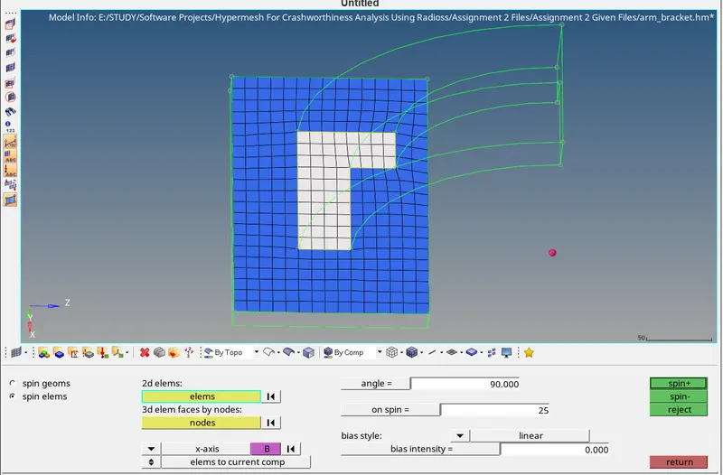
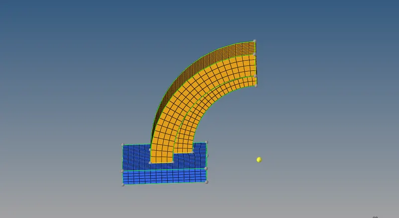
THE ARM CURVE WITH 3D HEXA MESH
- After completely meshing the Arm Curve Component, try to mesh the Arm straight component with 3D Hexa elements.
- Click on the Tool panel, select Faces tool upon entering into the toolbar then click on the components option and select the Arm Curve component and click on the Find faces button.
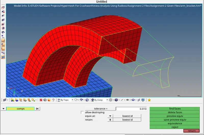
- The face of the Arm Curve will be displayed in red colour.
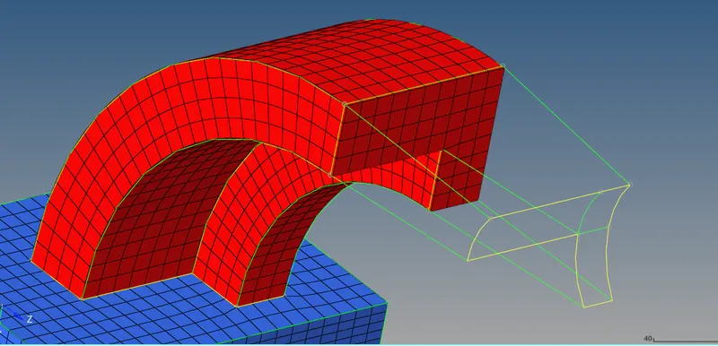
THE FACE OF THE ARM CURVE COMPONENT DISPLAYED IN RED COLOUR
- Mesh the face of the Arm Straight component with the same number of elements as the mesh with elements on the face of the Arm Curve.
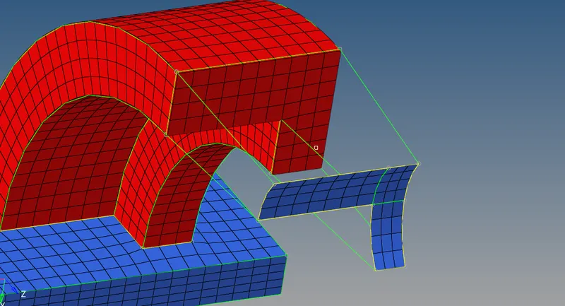
- After meshing the Arm Straight with the same number of elements, click on the 3D panel, select the Linear Solid tool.
- Upon entering into the toolbar, click on the From elements and select the elements on the face of the Arm curve then click on the To elements and select the 2D elements on the Arm Straight surface.
- Select the Alignment option and choose the Alignment same on the arm curve and arm straight elements as N1, N2 & N3 on the two surfaces. Click on the density and enter the value as 12 then click on the Solids button to create the 3D elements.
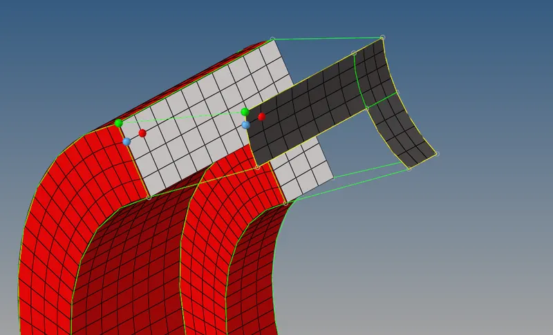
ALIGNMENT SELECTION ON THE ELEMENTS OF TWO SURFACES
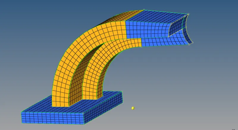
THE SOLIDS HAVE BEEN GENERATED ON THE ARM STRAIGHT CURVE COMPONENT SURFACE
- After completely meshing the Arm Straight component, create 3D Hexa mesh on the Boss component.
- To create a 3D Hexa mesh on the Boss surface, firstly mesh the Top surface of the boss component with 2D mesh.
- then click on the mesh button.
- After creating the 2D mesh, create a point along the surface by using the Project tool in the Tool panel in order to avoid any deviations of the mesh.
- Click on the Solid map tool, select the general option in it, click on the source geometry and select none option.
- Click on the Elements to drag option and select the 2D elements created on the top of the Boss surface.
- Click on the Destination geometry and select the bottom surface of the Boss component.
- Then click on the Along geometry and select the Lines option in it and click on the mesh button the 3D Hexa elements are created.
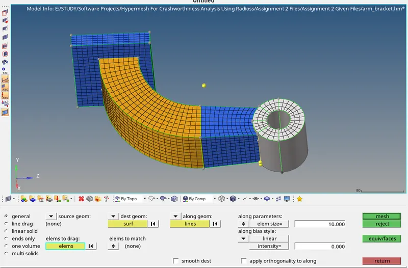
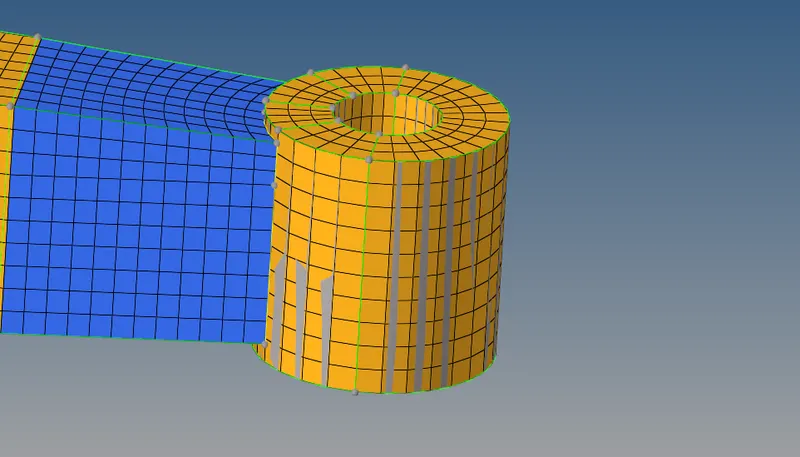
FINAL MESH ON THE BOSS MODEL
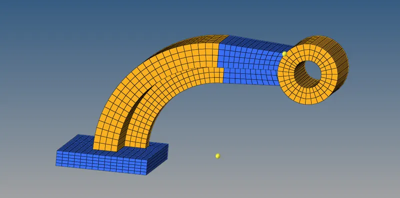
FINAL 3D MESHING OF AN ARM BRACKET MODEL
- Delete all the 2D elements once after the generation of 3D elements by using Delete tool in the Tool panel.
- After meshing all the components with 3D Hexa elements save the model in the .hm format by using the Save model option present in the File menu.
Conclusion:
- The engine file has been modified according to the calculations.
- The 1D elements have created on the surfaces.
- The 3D tetra mesh is generated on the given model.
- The 3D Hexa mesh is generated on the given model.
- The quality has been checked according to the given quality parameters.