Project 2
Aim: To generate a midsurface, perform the geometry cleanup on the extracted component and also to generate the mesh on the midsurface component and to assign thickness to the component within the given quality criteria
Tools used:
- The Automesh in the 2d panel
- The Auto cleanup in the geometry panel
- The Quick-edit in the geometry panel
- The quality index in the 2d panel
- The check elements in the tool panel
- The Mask in the tool panel
- The Edges in the tool panel
- The Translate in the tool panel
- The smooth in the 2d panel
- The Edit element in the 2d panel
- The Ruled in the 2d panel
- The Spline in the 2d panel
- The Replace in the 2d panel
- The Edge edit in the geometry panel
- The Surface edit in the geometry panel
- The Defeature in the geometry panel
- The Midsurface in the geometry panel
Procedure:
- Firstly, open the hypermesh software and select the profile as Radioss
- Then import the model by using the Import Model option present at the top of the window in the File menu
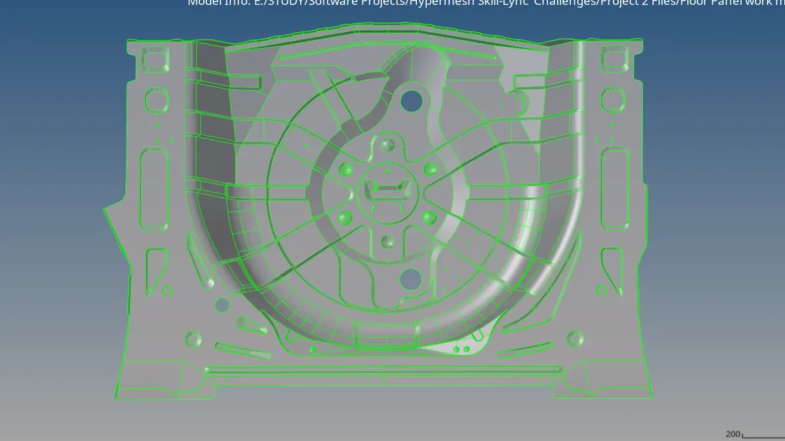
FLOOR PANEL MODEL AFTER IMPORTING INTO THE HYPERMESH WINDOW
- After importing the model extract the midsurface from the component by using the midsurface tool present in the geometry panel
- Click on the midsurface tool and select the auto midsurface in the options and in the extraction type option select "Offset+Planes+Sweeps"
- Select the entire surface with the help of the dropdown button by clicking on the displayed option
- The entire surface gets selected and click on the extract button, the midsurface will be extracted
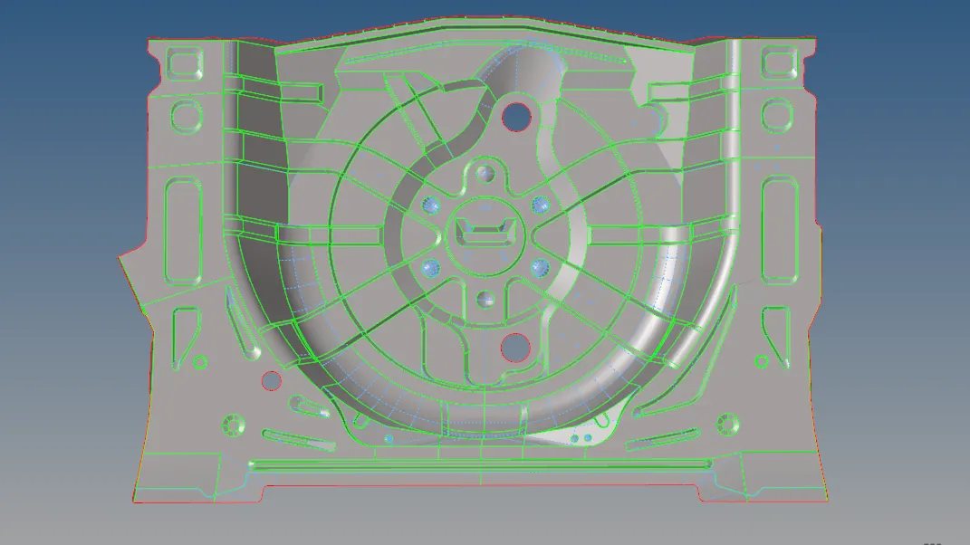
FLOOR PANEL MIDDLE SURFACE AFTER EXTRACTION AND AFTER GEOMETRY CLEANUP
- By using the defeature tool present in the geometry panel, remove pinholes, surface fillets etc on the midsurface
- Before performing the cleanup on the midsurface, make sure if any of the geometry gets disrupted while extracting the midsurface
- If any the geometry gets spoiled make sure to connect them by using Ruled and spline tools present in the 2d panel and also with the Quick edit tool present in the geometry panel
- Upon extracting the midsurface go to the Quick-edit tool present in the geometry panel
- Upon entering there are several options like toggle edge, add points etc, with the help of these tools perform cleanup on the extracted midsurface
- After the cleanup is done try to mesh the midsurface properly
- Go for the Automesh tool present in the 2D panel
- After entering into the Automesh panel, select the split surfaces one by one and mesh the surface
- Enter the target element size as 5, change the element type to 'mixed elements' and click on the align and size options and then click on the mesh
- The surface gets meshed and the elements are created on the surface
- Try to mesh the whole surface one by one by selecting the surfaces on the component
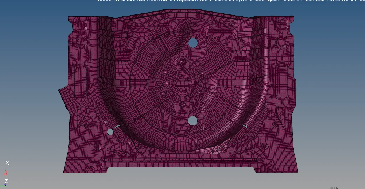
FLOOR PANEL AFTER MESHING THE SURFACE
- After meshing the component properly, check for the quality by selecting the quality index on the 2d panel
- Select the quality index tool in the 2d panel and check for the quality of the mesh
- There are a lot of options present in the quality index like node optimise, element optimise swap edge etc
- By using these tools, clear all the failed elements
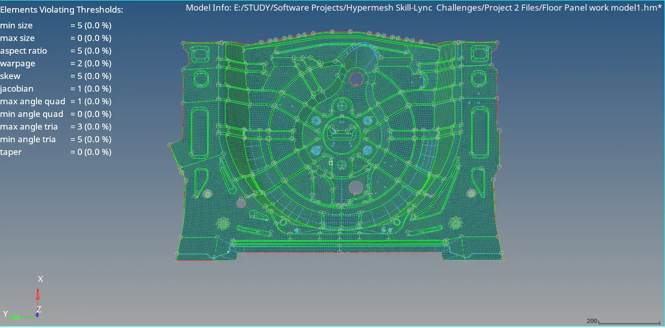
THE MESH WHEN CHECKED FOR FAILED ELEMENTS IN THE QUALITY INDEX
- After clearing the failed elements, go for check elements tool present in the tool panel
- After entering the check elements tool, there are a lot of options like jacobian, skewness, aspect ratio etc.
- Place the given quality criteria places in their respective places and check for the failed elements
- If there are any failed elements present, try to clear them by using quality index tool in the 2d panel
- By using the translate option in the tool panel try to clear the failed elements
- By using the mask tool in the tool panel try to mask the surfaces or elements wherever required for any process
- Use replace option to replace the edges of the elements
- Use edge edit tool to toggle or replace the edges on the surface wherever required for meshing
- use surface edit for offsetting the surface from the parent component wherever required
- The smooth tool is used to smoothen the elements after the quality process is performed
- The edges tool present in the tool panel used to remove free edges on the midsurface
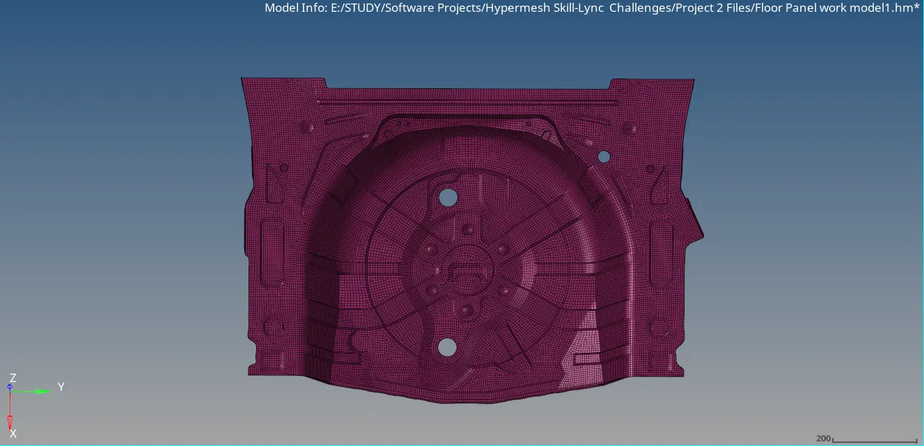
THE FLOOR PANEL MIDSURFACE FINAL MESH AFTER CLEARING ALL THE FAILED ELEMENTS
- After removing all the failed elements and performing quality process apply the thickness
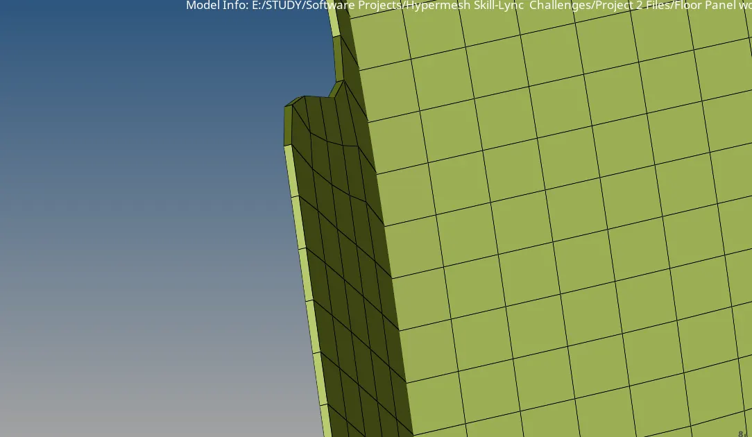
THE THICKNESS REPRESENTATION OF FLOOR PANEL MIDDLE SURFACE
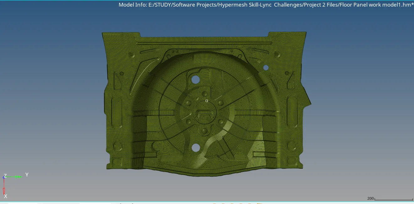
THE FLOOR PANEL MIDDLE SURFACE ELEMENTS AFTER ASSIGNING THICKNESS
- After assigning the thickness for the midsurface try to save the model
- Use the save model option in the File menu at the top of the window
Conclusion: The midsurface has been extracted from the given component, the geometry cleanup is done on the extracted surface, the mesh is generated on the midsurface and it is checked for quality within the given quality criteria parameters and the thickness has been assigned