Week 9 Challenge
Aim:
- To create 2 sliders for the 2 undercuts present in the CPU fan case model.
- To create inserts in the model wherever required.
Procedure:
In previous challenges we have created the mold blocks for the door bezel as shown below:
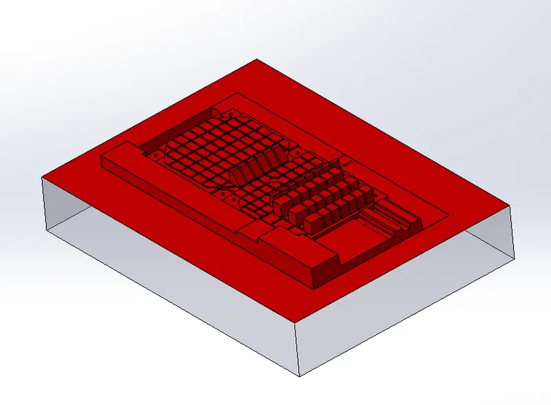
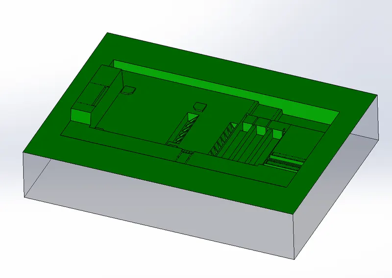
- Activate the core block first, then select a reference surface to choose as reference as shown below,
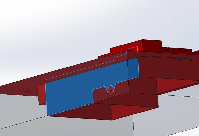
- Draw a sketch using rectangle feature as shown below.
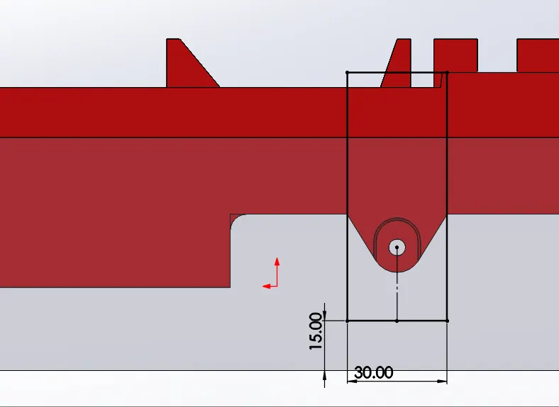
- Click split command and select the reference plane and the sketch created as the trim / split tool and the for the body select the core block and click cut bodies.
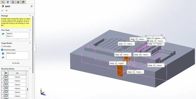
- Now from the list of resulting bodies select the body needed to be split up and deselect consume cut bodies option and click 'OK'.
- Create another sketch on the face of the split body ans extrude as shwon below,
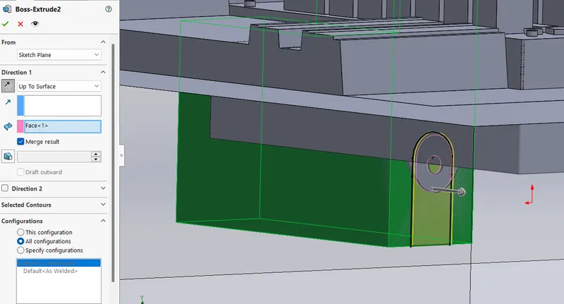
- Now here 2 seperate bodies are created. So in every step show take care about choosing the feature scope as necessary.
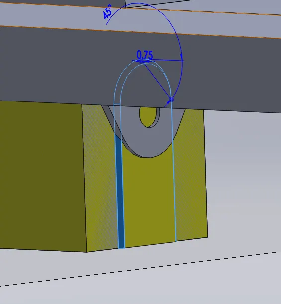
- Create a chamfer as required.
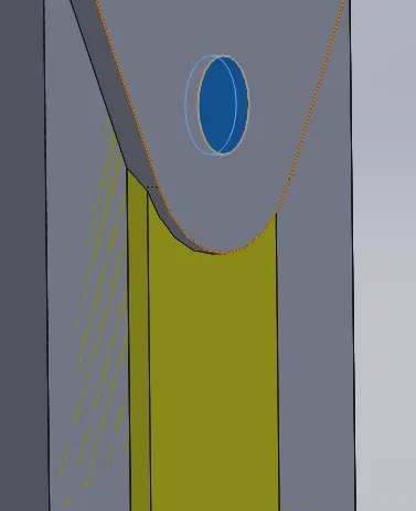
- Again create the circular profile with extrude command.
- Now select a surface sa shown below draw a rectangle and extrude upto the top surface of the split body.
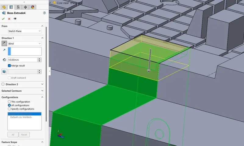
- Move the top side surface to appropriate distance in or to create the wedge for thr slider and cut using cut extrude command.
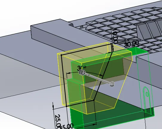
Now create 2 rectangles to make a collar and cut the unwanted regions.
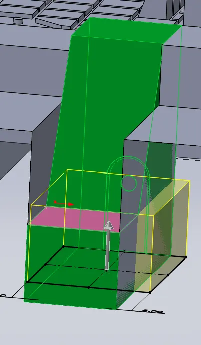
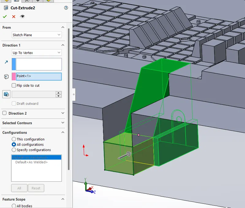
- Create a copy of the slider block and save it as a parasolid file.
- Then using combine command subtract the region from the cavity block.
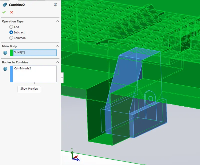
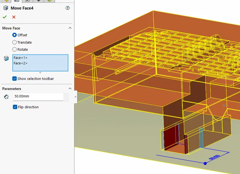
- Click move face command and select the bottom edges for moving till the collar edge of the slider.
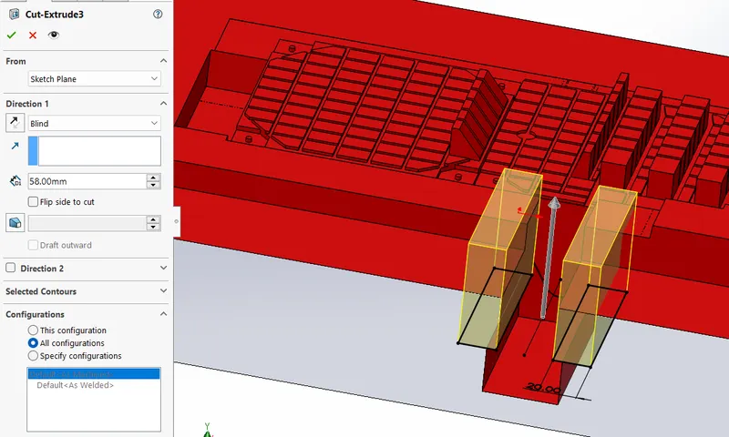
- Now cut extrude the region shown below from the vertex of the wedge of the slider.
- Now activate the cavity block for editing.
- Import the slider part which is already saved as parasolid file.
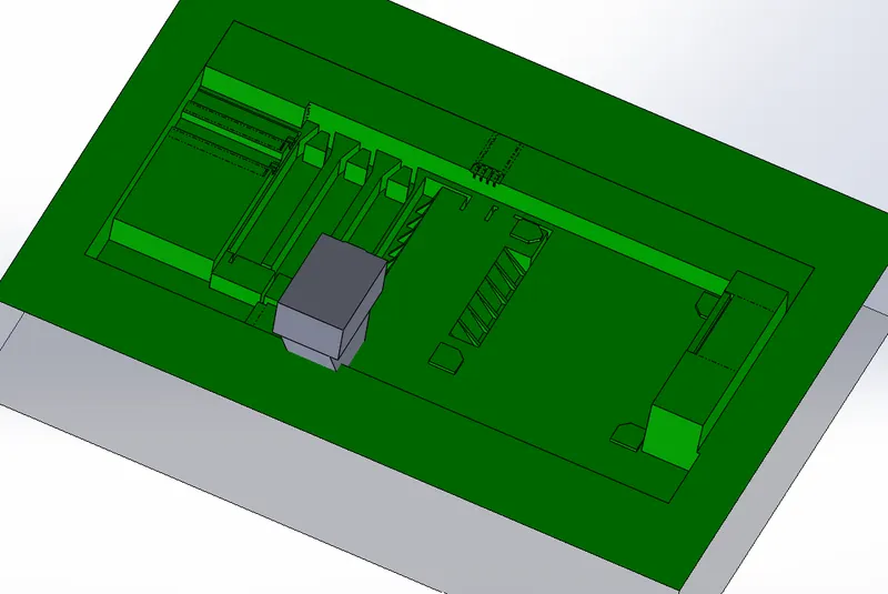
- Now create a rectangular sketch and extrude in both direction as shown in below figure.
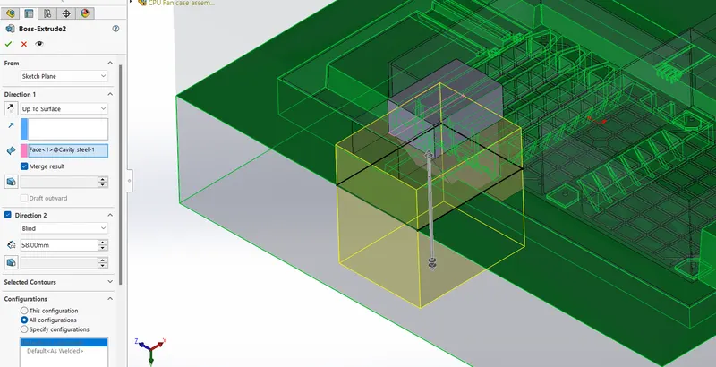
- In order to remove the unwanted region from the cavity block, click conbine feature and seletech substract option and click ok.
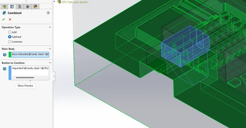
- Now create new part in the assemble and name it as slider.
- Import the parasolid part created and save the file.
- Rename the part file as slider_01
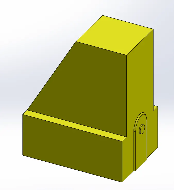
- Follow the same procedure and create the slider for the other region also
- Save the part file as Slider_02
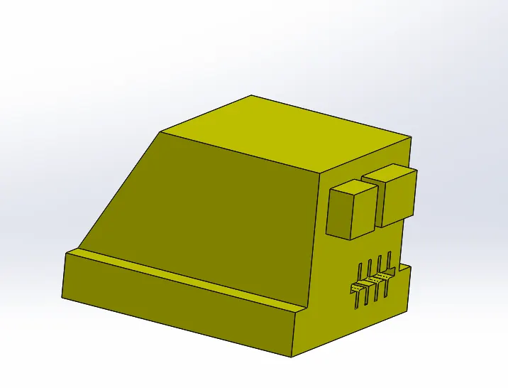
Now we have to create the inserts for the blokcs.
There are a region with deep cut which cannot be create without the inserts as shown in below sectional view of blocks.
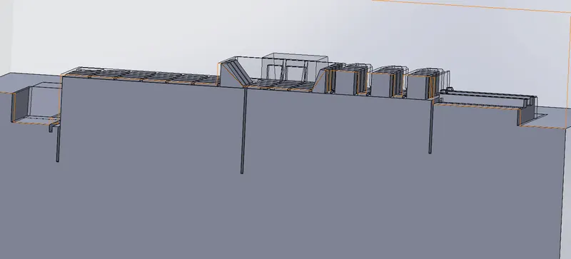
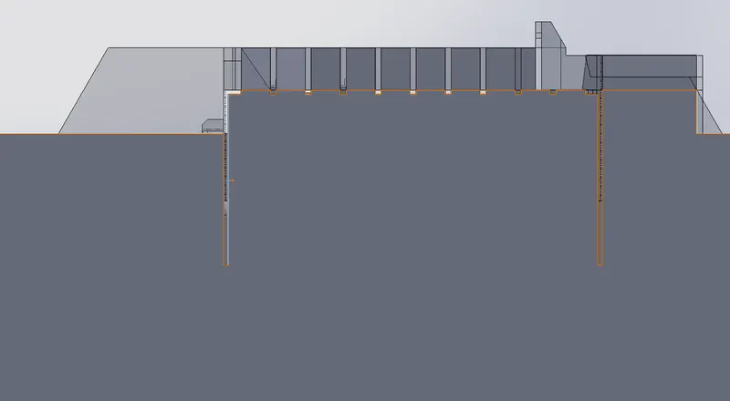
First create a reference plane at a offset distance 20mm from the bottom most surface of the component.
Draw a 2 different sketch of triangles on the reference plane as shown below.
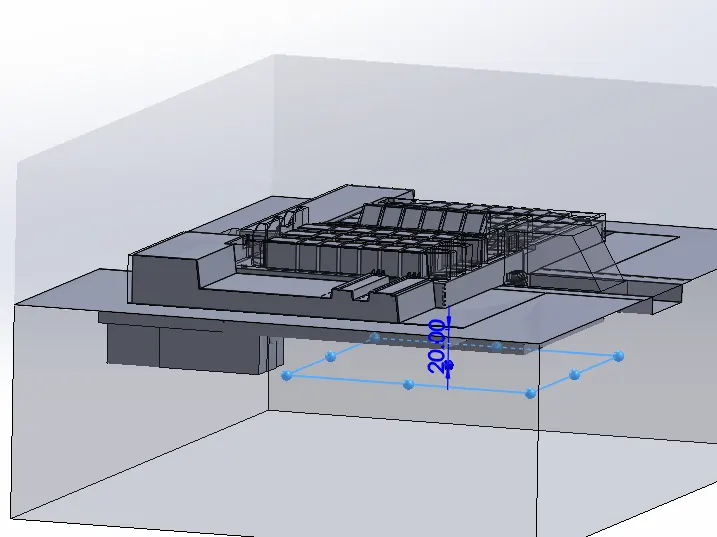
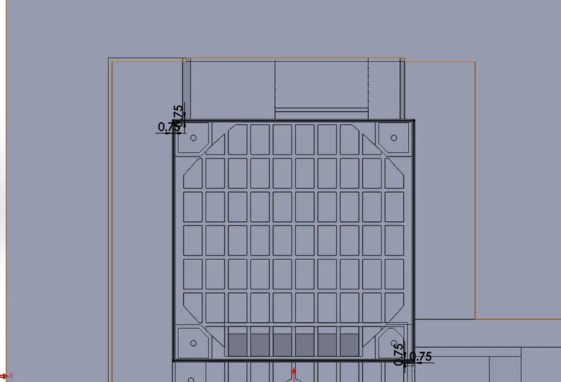
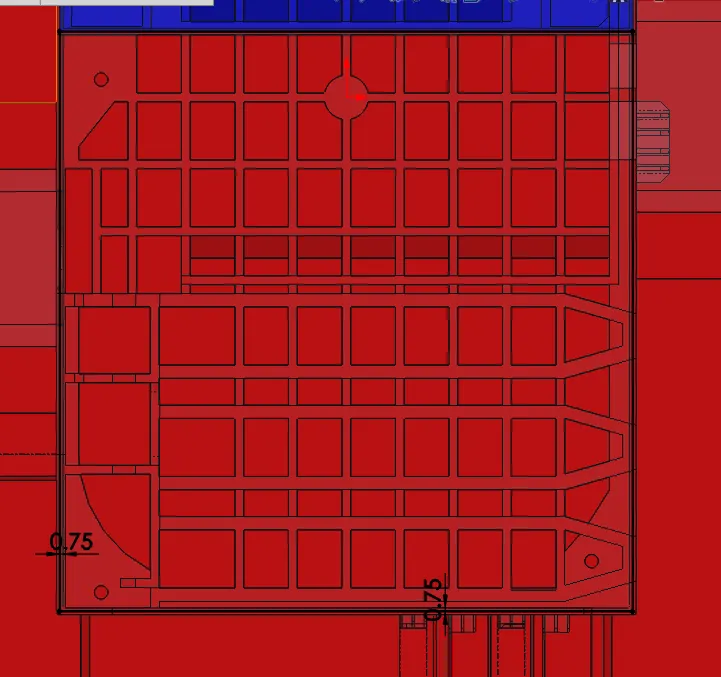
Click split command and select the first rectangle sketch along with the plane as the tirm tool
Select the required region and follow the same procedure for the other sketch also.
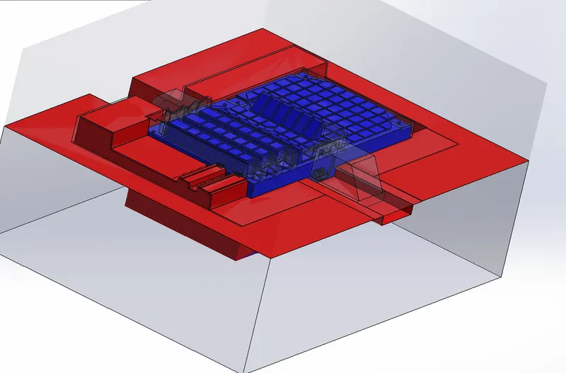
Change the appearance of the blocks as above.
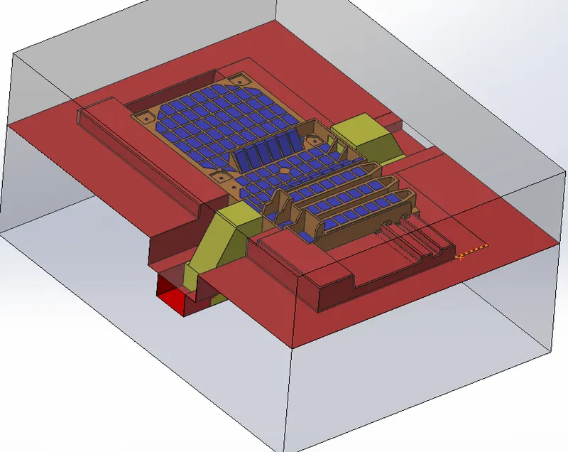
Hence the inserts and the sliders are created for the mold block.
Conclusion:
The sliders for the mold block are created and explained.
The inserts required are also created.