Week 9 - Challenge 3 - Bumper
BUMPER
Detailed report of BUMPER Close surface creation:
- TOOLING AXIS CREATION.
- DRAFT ANALYSIS OF CLASS A & FINAL COMPONENT.
- TREE STRUCTURE.
- ALL THE VIEWS.
TOOLING AXIS CREATION:
MAIN TOOLING AXIS:
The main tooling axis is essential for the bumper design process, especially for thickening the part. It ensures proper core and cavity fixation and facilitates mold opening and closing without damaging the part during ejection.
AXIS CREATION:
- Create a Point:
Start by defining a point on the edge of the Class A surface using the "Point on Curve" method.
- Create the Tooling Axis Line:
Use the Point-Direction method to create a line in the X-direction. This line becomes your main tooling axis.
- Color the Tooling Axis:
Assign a color to the tooling axis to easily identify and differentiate it in your design.
This process ensures the proper alignment and function of the mold during the manufacturing process.
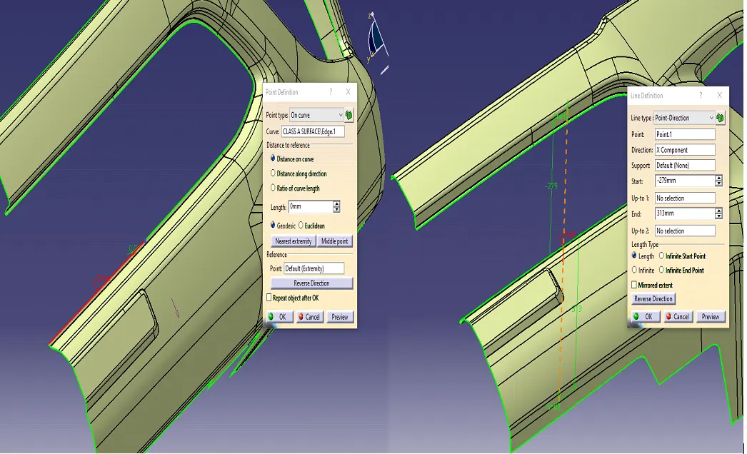
POINT AND LINE CREATION
DRAFT ANALYSIS OF CLASS A & FINAL COMPONENT:
CLASS A DRAFT ANALYSIS:
DRAFT ANALYSIS OF CLASS A & FINAL COMPONENT:
CLASS A DRAFT ANALYSIS:
CLASS A DRAFT ANALYSIS:
Is a critical step in plastic part design to ensure that the visible, outermost surface (Class A surface) is designed in such a way that it can be easily released from the mold during the injection molding process. The analysis focuses on ensuring that the Class A surface has sufficient draft angles to allow for smooth ejection from the mold without causing defects or damage.
Purpose of Draft Analysis on Class A Surface:- Ensure Smooth Ejection: The Class A surface, being the outer visible part of the component, must have a slight draft (angle) on vertical or near-vertical surfaces. This angle allows the part to be ejected without getting stuck, preventing damage to the surface finish.
- Prevent Surface Deformation: Without the proper draft, parts may experience unwanted deformation, stretching, or scuffing when removed from the mold. The draft ensures the smooth flow of the part out of the mold cavity.
- Improve Moldability: Draft analysis helps identify regions of the Class A surface that might need adjustments to their angle, enabling easier and more efficient molding. The right draft angles reduce wear on the mold and improve its lifespan.
- Maintain Aesthetic Quality: The Class A surface is often the most visible part of the plastic part (such as a bumper), so any defects or marks caused by poor ejection could significantly affect the visual quality. Proper draft ensures a flawless surface finish.
- Optimize Manufacturing Process: By conducting draft analysis, designers can adjust the geometry early in the design phase, avoiding the need for costly design revisions later in the process. It ensures that the Class A surface is molded correctly and can be easily ejected, improving overall efficiency.
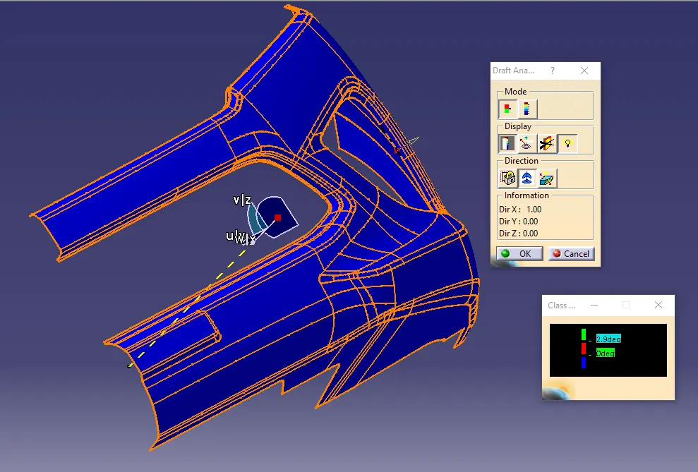
CLASS A DRAFT ANALYSIS
- Ensure Smooth Ejection: The Class A surface, being the outer visible part of the component, must have a slight draft (angle) on vertical or near-vertical surfaces. This angle allows the part to be ejected without getting stuck, preventing damage to the surface finish.
- Prevent Surface Deformation: Without the proper draft, parts may experience unwanted deformation, stretching, or scuffing when removed from the mold. The draft ensures the smooth flow of the part out of the mold cavity.
- Improve Moldability: Draft analysis helps identify regions of the Class A surface that might need adjustments to their angle, enabling easier and more efficient molding. The right draft angles reduce wear on the mold and improve its lifespan.
- Maintain Aesthetic Quality: The Class A surface is often the most visible part of the plastic part (such as a bumper), so any defects or marks caused by poor ejection could significantly affect the visual quality. Proper draft ensures a flawless surface finish.
- Optimize Manufacturing Process: By conducting draft analysis, designers can adjust the geometry early in the design phase, avoiding the need for costly design revisions later in the process. It ensures that the Class A surface is molded correctly and can be easily ejected, improving overall efficiency.
CLASS A DRAFT ANALYSIS
FINAL COMPONENT DRAFT ANALYSIS:
Draft analysis on the final component surface ensures that the visible part of the plastic component is molded with proper draft angles, allowing for smooth, defect-free ejection from the mold. This step helps maintain aesthetic quality, optimize manufacturing processes, and reduce potential defects during the molding process.
DRAFT ANALYSIS :
Angle Evaluation :
The draft angle is usually between 1-3 degrees, but it depends on the part geometry, material, and molding process. Use Draft analysis tools in CATIA software to visualize areas of the Class A surface that lack the required draft angle. The draft angle is usually between , but it depends on the part geometry, material, and molding process. Use in CATIA software to visualize areas of the Class A surface that lack the required draft angle.
Checking for Under-cuts:
Under-cuts or sharp vertical walls without draft are problematic for mold release. Draft analysis identifies these areas so they can be corrected or designed with a more suitable angle.
Visual Feedback:
CATIA software typically provides color-coded feedback to highlight regions that do not meet the required draft angle. Green areas show acceptable angles, while red or yellow indicate areas that need modification.
Adjustments:
If certain areas fail the draft analysis, designers can adjust the part's geometry (such as increasing the angle or modifying surface features) to ensure easy mold release.
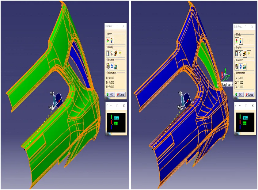
FINAL COMPONENT DRAFT ANALYSIS
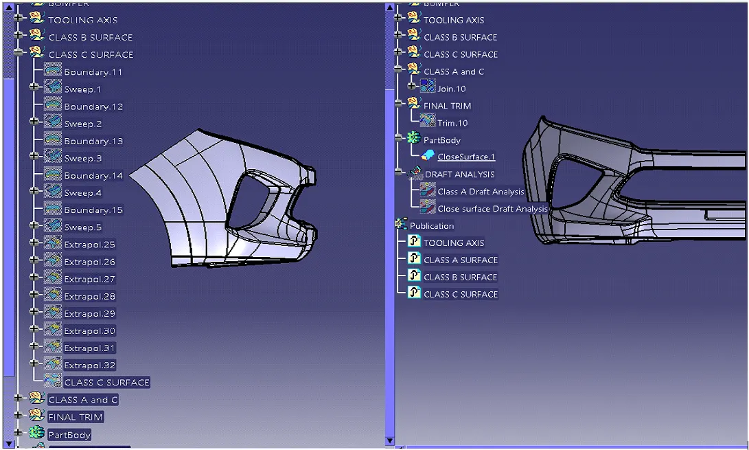
TREE STRUCTURE:
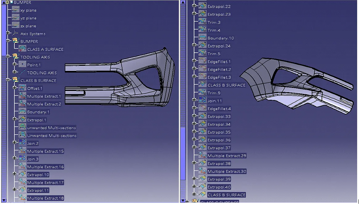
ALL THE VIEWS OF PLASTIC COMPONENT:
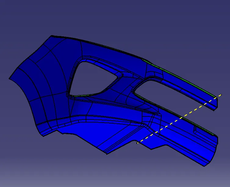
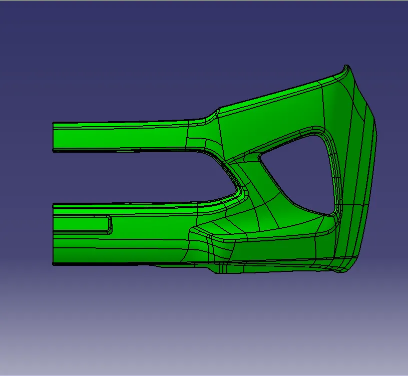
Solid model with the proper color code of the draft angle in various orientations, In all the views.
ISOMETRIC VIEW
BACK VIEW
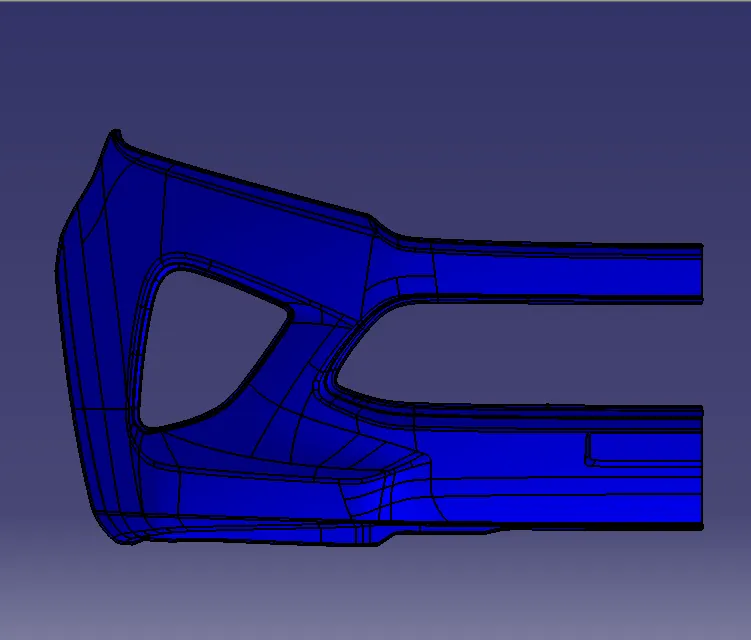
FRONT VIEW
SIDE VIEW
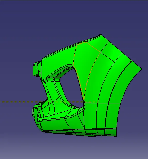
BOTTOM VIEW
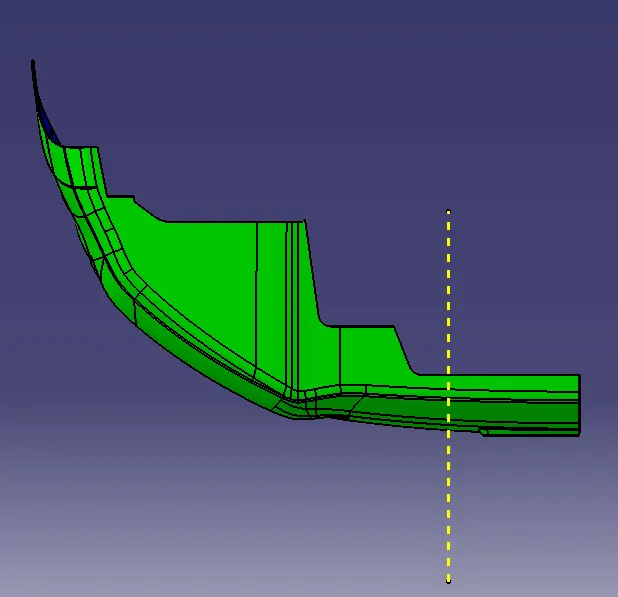
TOP VIEW
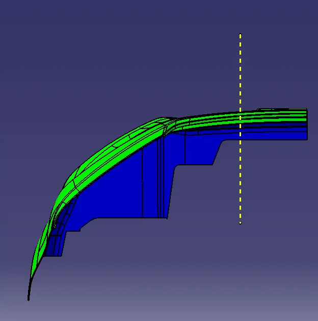
NOTE: I Have attached the CATPart file submitted as an using the below Browse option for your reference.
FINAL COMPONENT DRAFT ANALYSIS
TREE STRUCTURE:
ALL THE VIEWS OF PLASTIC COMPONENT:
Solid model with the proper color code of the draft angle in various orientations, In all the views.
ISOMETRIC VIEW
BACK VIEW
FRONT VIEW
SIDE VIEW
BOTTOM VIEW
TOP VIEW
NOTE: I Have attached the CATPart file submitted as an using the below Browse option for your reference.