Week 10 - Challenge 2- Attachment Feature Creation (Dog House)
DOG HOUSE DESIGN
Introduction
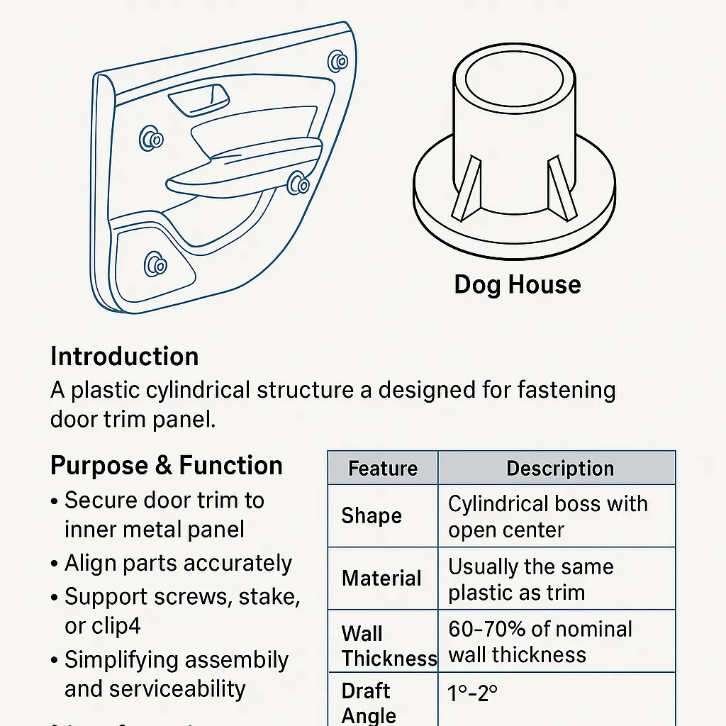
In automotive interior systems, especially in the Door trim panel, a component called the Dog House plays a vital role in ensuring a secure and stable assembly. It is a plastic cylindrical structure designed to hold trim parts in place by using different fastening methods.
Purpose & Function
The Dog House is primarily used to:
- Secure the door trim to the inner metal panel of the door.
- Align parts accurately to avoid misfit or rattle.
- Support screws, stakes, or clips to hold parts firmly.
- Simplify assembly and serviceability during manufacturing or after-sales repair.
| Shape | Cylindrical boss with open center (for screw/stake entry) |
|---|---|
| Material | Usually the same plastic as trim (PP, ABS, PC-ABS) |
| Wall Thickness | 60–70% of nominal wall thickness to avoid sink marks |
| Draft Angle | 1°–2° to ensure smooth ejection from mold |
| Rib Reinforcements | Often added to strengthen the structure and prevent deformation |
Design Characteristics
Manufacturing Techniques
Dog Houses can be fixed to base components using:
- Heat Staking – Melting the plastic slightly to bond with the trim.
- Ultrasonic Welding – Using vibrations to melt and join plastic surfaces.
- Self-Tapping Screws – Screwed directly into the boss for tight fixing.
Visual Layout Description
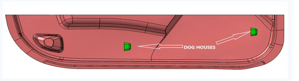
A typical Door Trim Panel contains multiple Dog Houses placed at strategic positions such as
- Near clip areas
- Around the armrest and handle zones
- Along the periphery of the panel
AIM
Create the Dog House for the Door Trim considering the design rules mentioned in the video. Consider the thickness of the part to be 2.5 mm.
- "C" is where the doghouse contacts the backside of the surface
- Doghouse wall thickness at the intersection of the part wall ( C ) should be 40% or less than the main wall stock ( T ).
- The height of ( B ) should be between 3.0 – 6.0 mm
Procedure for Creating Tooling Axis
1. Class - A Tooling Axis
2. Side Core Tooling Axis
- Manually Adjust the Compass:
Begin by manually rotating the compass to explore potential tooling directions. Choose a direction that provides maximum clearance for the majority of surfaces.
- Evaluate Optimal Tooling Direction:
Through visual analysis, determine the most suitable tooling direction. In this case, the Y-axis appears to offer the best clearance with minimal obstructions.
- Surface Extraction and Point Creation:
Extract a relevant surface from the component and identify a central location. Create a midpoint on this surface for further reference.
1. Class - A Tooling Axis Creation
Point Creation
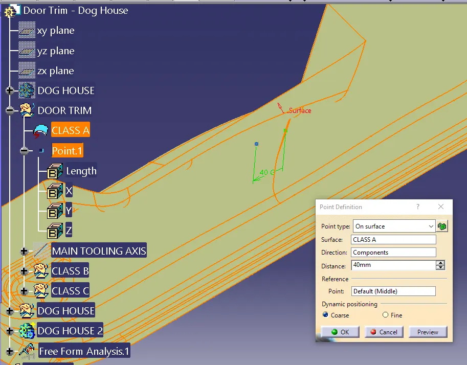
- Use the Point Definition tool to create a point by selecting the "On Surface" option. Choose an appropriate surface where the point needs to be placed.
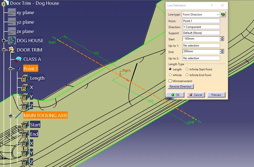
- Once the point is created, generate a line that will act as the main tooling axis. Use the Point and Direction method, selecting the previously created point and defining the direction along the Y-axis.
2. Side Core Tooling Axis
Shell Face Extraction
- The shell face of the geometry will be extracted first.
- This operation isolates the specific surface or region of interest from the full model.
- It helps in focusing only on the surface required for further operations like point or line creation.
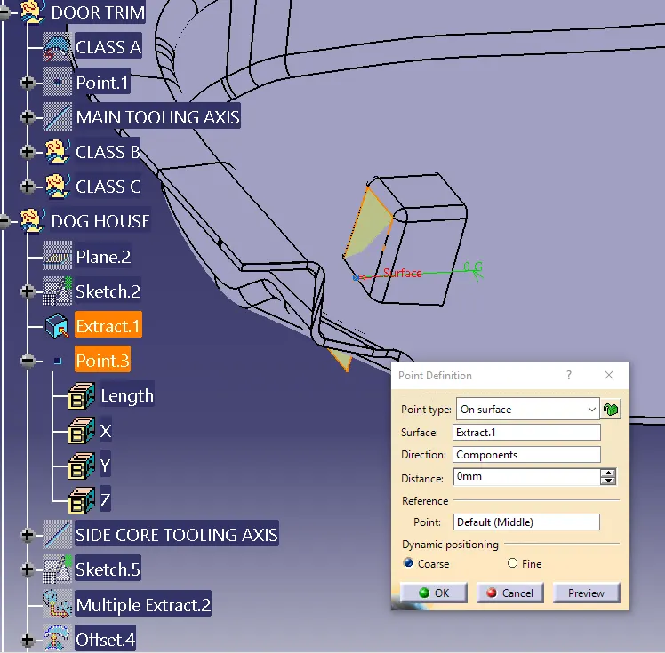
Surface Point Creation
- After extracting the shell face, the next step is creating a point on the surface.
- This is done using the "Point on Surface" creation method.
- It allows for accurate positioning of a reference point directly on the selected surface.
- This point will serve as a reference or anchor for the line to be created next.
Line Creation Using Normal to Surface
- Once the point is created on the surface, proceed to create a line.
- Use the "Normal to Surface" method for line creation.
- This method generates a line that is perpendicular (normal) to the surface at the given point.
EXTRACT
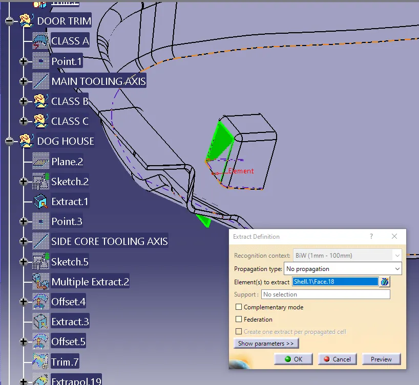
POINT CREATION
LINE CREATION
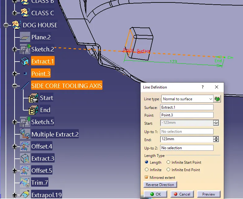
vThe above three steps are also used to create the Side Core Tooling Axis 2.
DRAFT ANALYSIS
Draft Analysis is a process used to confirm whether a part can be easily removed from the mold during manufacturing. It helps verify that all vertical surfaces have the required draft angle, usually 3° or more, to prevent sticking or damage during ejection.
How to Perform Draft Analysis:
Prepare the Part View
– Set the display to Customized Parameters and select Shading with Material for better visibility.
Launch the Tool
– Go to Insert > Draft Analysis to open the command.
Set Draft Direction
– Use the Compass, align it with the Tooling Axis, and lock it to set the pull direction.
Apply Analysis
– Click on the part to highlight draft conditions using color indicators.
Color Legend:
Green → Acceptable (Positive Draft)
Red → Critical (Zero Draft)
Blue → Problematic (Negative Draft)
Why It's Important
vEnsures the part can be ejected without damage
vHelps avoid costly mold changes or part defects
vEssential for all injection molded and cast components
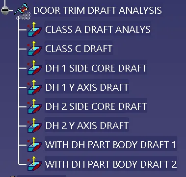
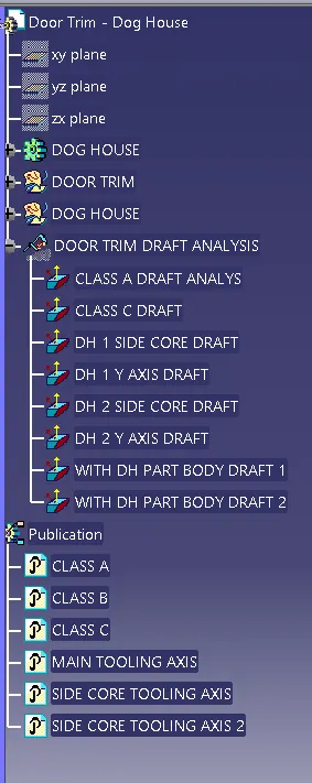
The Draft Analysis includes the following:
- CLASS A DRAFT
- CLASS C DRAFT
- DOG HOUSE 1 SIDE CORE DRAFT
- DOG HOUSE 1 “Y” AXIS DRAFT
- DOG HOUSE 2 SIDE CORE DRAFT
- DOG HOUSE 2 “Y” AXIS DRAFT
- WITH DH PART BODY DRAFT 1
- WITH DH PARTBODY DRAFT 2
CLASS A DRAFT
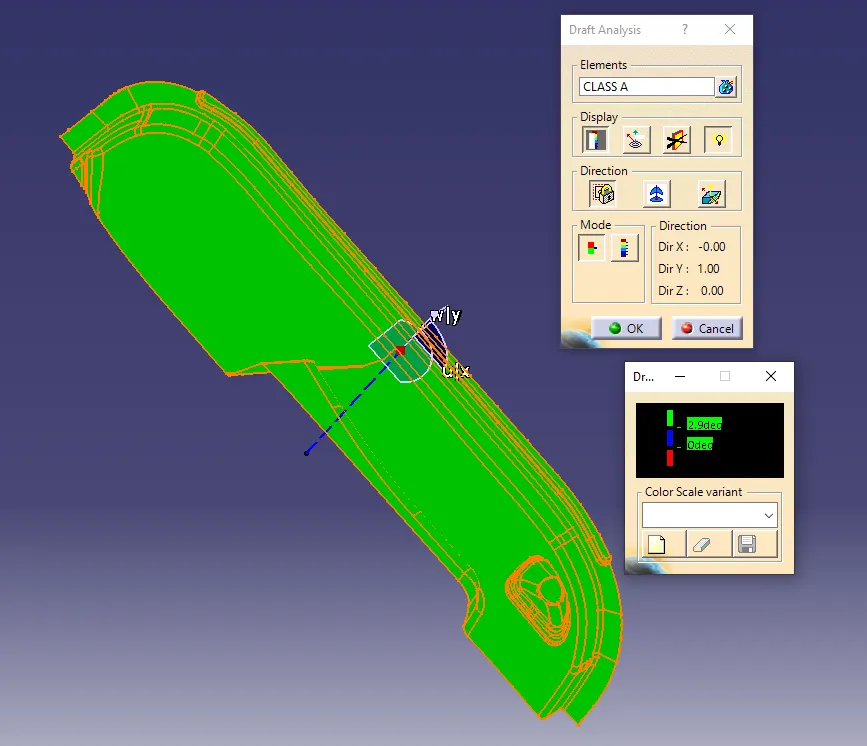
vIn this Class A surface draft analysis angle is 2.9 degree.
CLASS C DRAFT
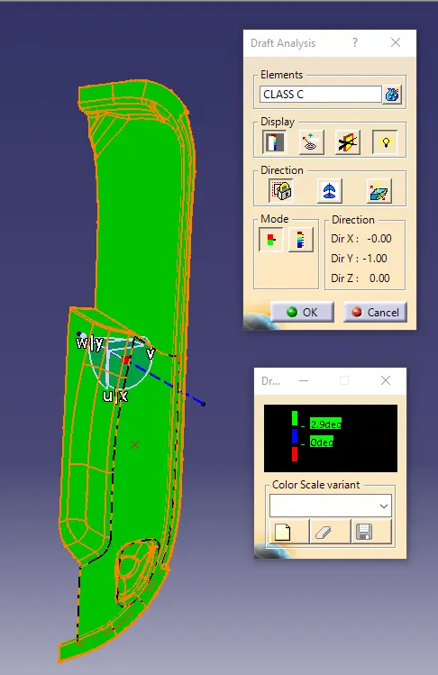
vIn this Class C surface draft analysis angle is 2.9 degree.
DOG HOUSE 1 SIDE CORE DRAFT
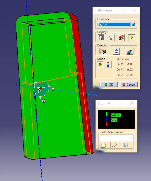
vIn this Dog house 1 side core draft analysis angle is 0.48degree.
DOG HOUSE 1 “Y” AXIS DRAFT
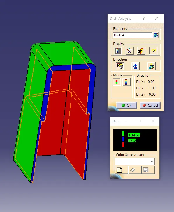
vIn this Dog house 1 “Y” axis draft analysis angle is 1.49degree.
DOG HOUSE 2 SIDE CORE DRAFT
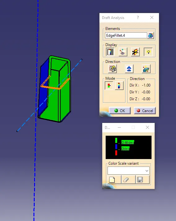
vIn this Dog house 2 side core draft analysis angle is 0.48degree.
DOG HOUSE 2 “Y” AXIS DRAFT
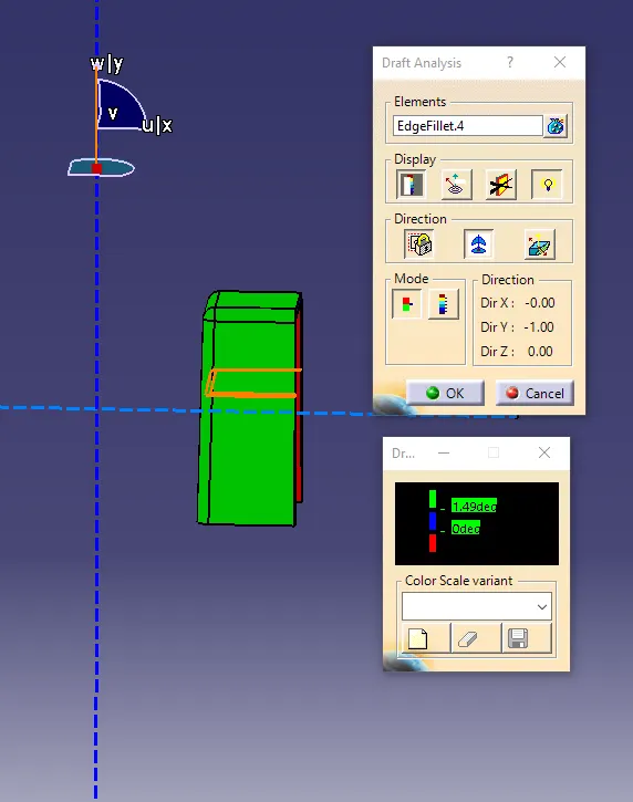
vIn this Dog house 2 “Y” axis draft analysis angle is 1.49degree.
WITH DH PART BODY DRAFT 1
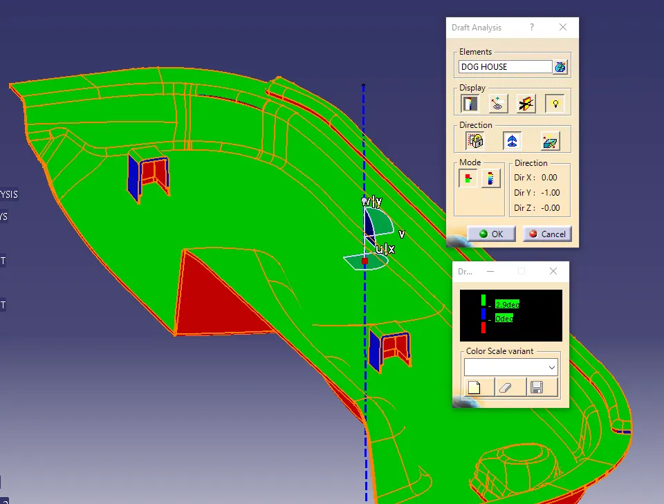
vIn With Dog house part body draft 1 analysis angle is 2.9degree.
WITH DH PARTBODY DRAFT 2
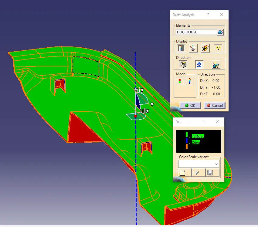
vIn With Dog house part body draft 2 analysis angle is 1.49degree.
vAll the part body close surface are cleared the draft analysis.
PUBLICATIONS
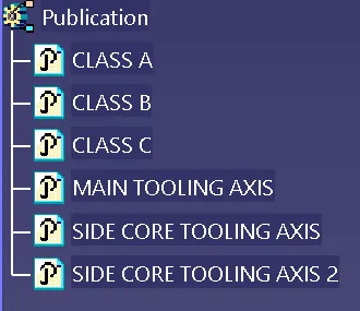
SKETCHES
- All the sketches are Iso -constrained.
- All the sketches are created under the Geometrical Set, Sketch presence inside of Geometrical set with proper name.
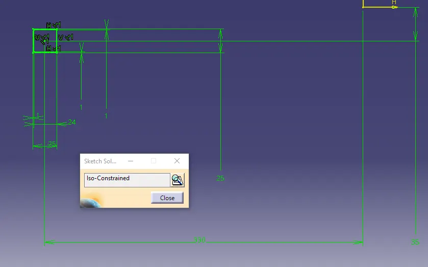
SKETCH 1
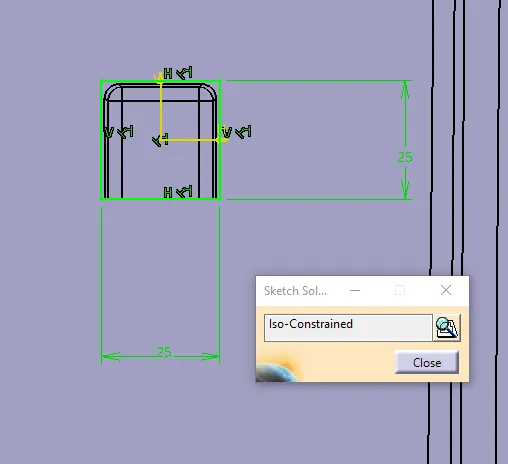
SKETCH 2
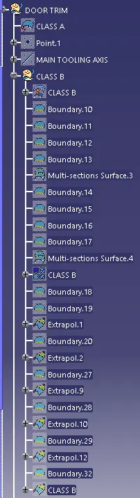
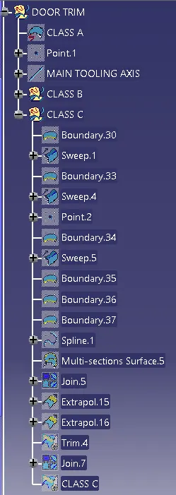
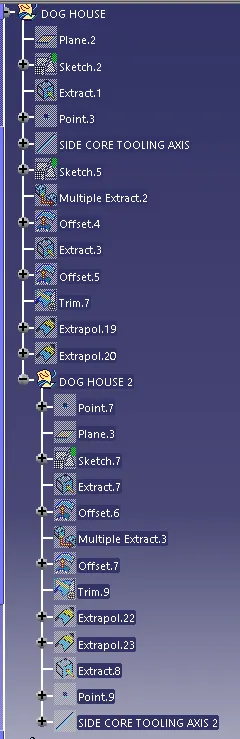
ALL THE TREE STRUCTURES
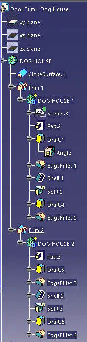
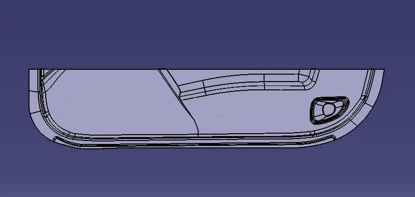
ALL THE VIEWS OF DOOR TRIM DOG HOUSE
ISOMETRIC VIEW
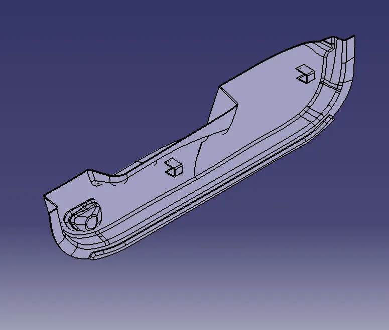
FRONT SIDE VIEW
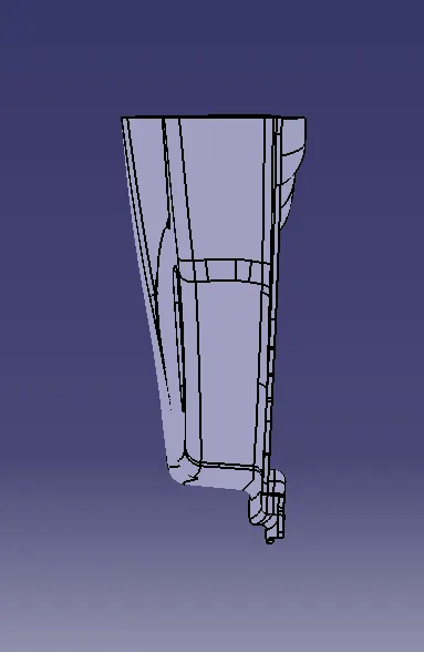
BACK SIDE VIEW
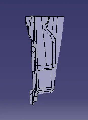
RIGHT SIDE VIEW
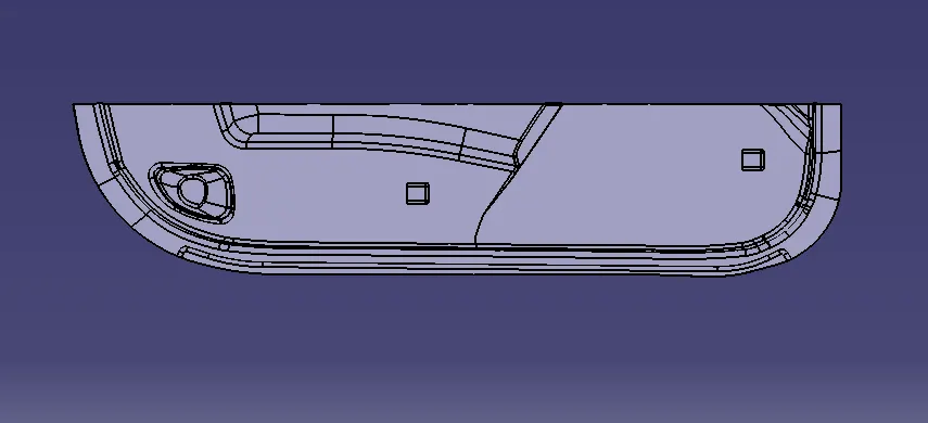
LEFT SIDE VIEW
Conclusion
I have successfully created CLASS B and C surfaces using the given CLASS A surface of the door trim created main and side core tooling axis. Performed draft analysis the the final component and the dog house.
NOTE: The Class-A surface had some errors, which is why the Draft Analysis showed red color indications. I have informed the host, Mr. Raseeth.