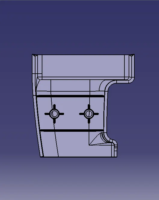
Week 10 - Challenge 1- Attachment Feature Creation (Ribs & Screw Boss)
RIBS AND SCREW BOSS
AIM:
To create the attachment feature (Ribs & Screw Boss) for the door handle.
OBJECTIVE:
l To ensure the model follows standard design rules for Rib and Screw Boss creation.
l To create the Tooling Axis for the component.
l To perform Draft Analysis to verify manufacturability.
DESIGN METHODOLOGY:
Tooling Axis Creation:
The tooling direction is the path along which the part is ejected from the mold. It is essential for defining the opening and closing direction of the mold, which consists of two halves: the Core and the Cavity. The Core side moves away from the Cavity side along the tooling direction, forming the parting line and enabling proper demolding.
Point creation:
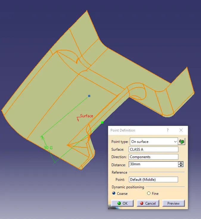
l Create the point by using the Point Definition in On surface point creation method.
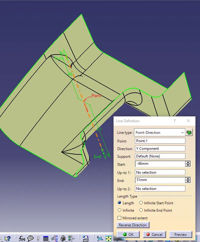
l After that we create the line for the purpose of main tooling axis, that line will be created in Point Direction method based on the point in Y- Direction.
Line creation:
Draft Analysis :
The Draft Analysis allows the user to easily analyze a part for proper draft angle. A Draft Angle describes the amount of taper for molded or cast parts perpendicular to the parting line. Draft Analysis is applicable for 3D part models. To create a draft analysis for any 3D part file, the user needs to select part/surface and select the pull direction. You can change the pull direction.
The same Tooling Axis was used for performing Draft Analysis on both the Class-A surface and the Ribs & Screw Boss design, but with different draft angle degrees applied to each as per design requirements.
CLASS-A DRAFT ANALYSIS
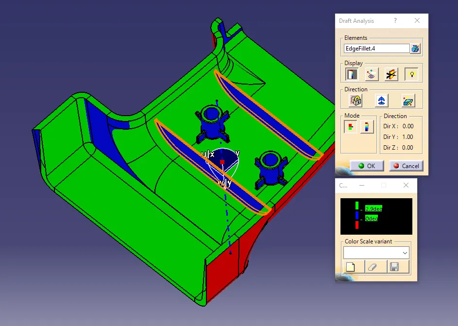
l In the above figure, the ribs, bosses, and gussets appear blue because a 2.9-degree draft angle was applied to the main body, while these features only had a 0.5-degree draft, causing a draft analysis mismatch.
RIBS AND SCREW BOSS DRAFT ANALYSIS
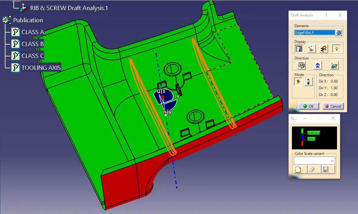
l To resolve this, in the figure below, I adjusted the draft angle to 0.49 degrees, ensuring that the entire component, including the ribs, bosses, and gussets, meets the draft requirements and appears acceptable in the draft analysis.
ALL THE SKETCHES :
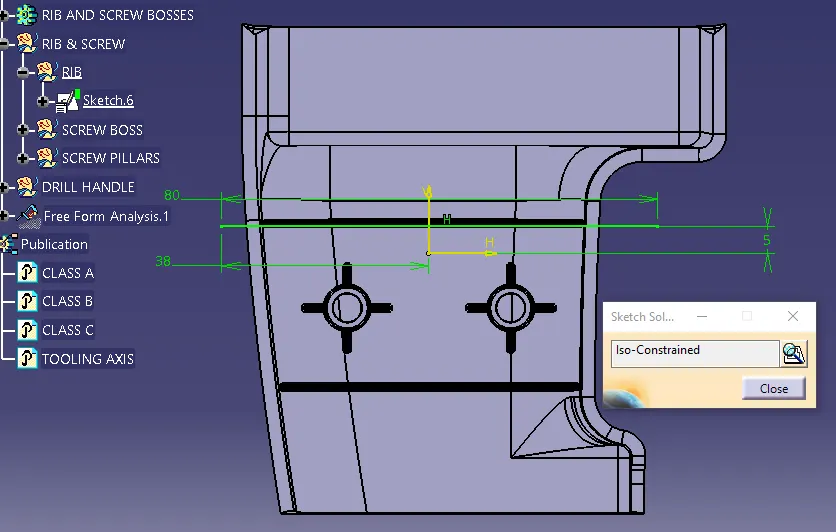
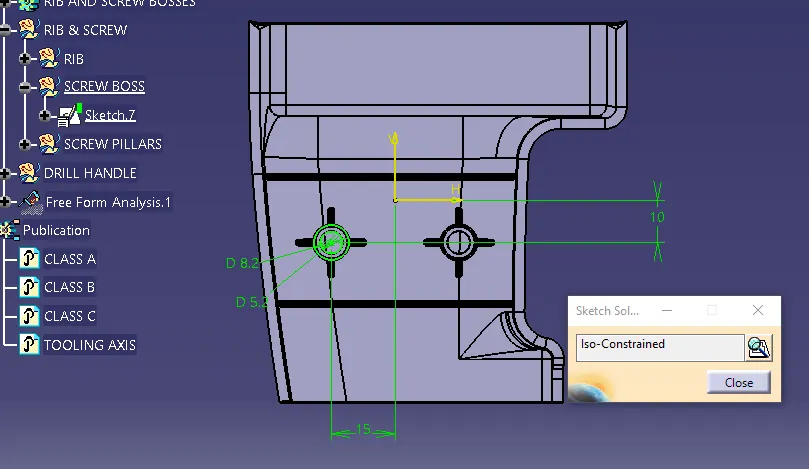
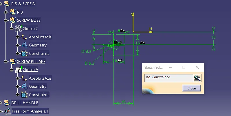
All sketches shall be fully defined (ISO-constrained).
The rib and screw boss design consists of the following three sketches:
1. Rib.
2. Screw Boss.
3. Screw Boss Pillars.
RIB
SCREW BOSS
SCREW BOSS PILLARS
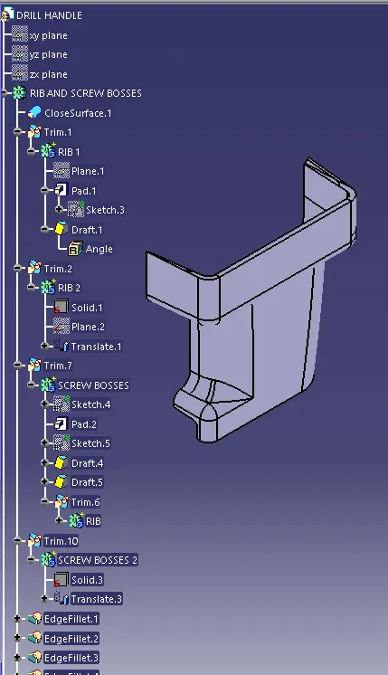
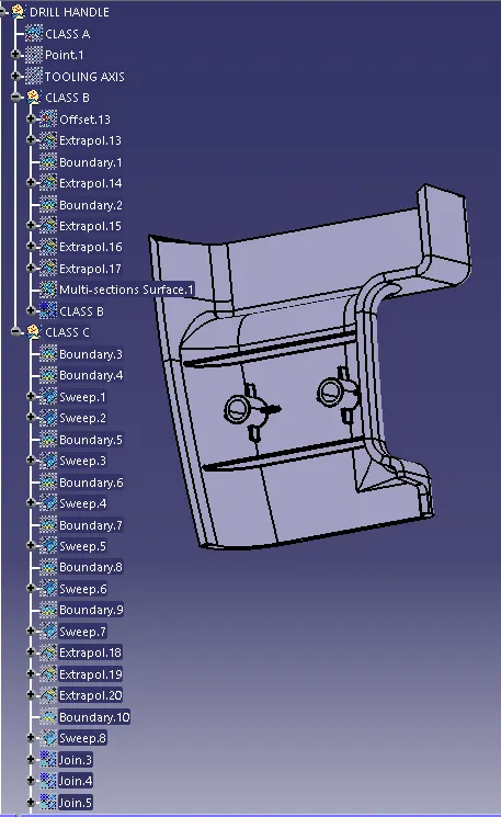
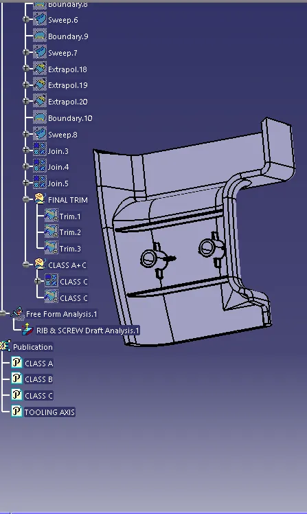
TREE STRUCTURES:
ALL THE VIEWS:
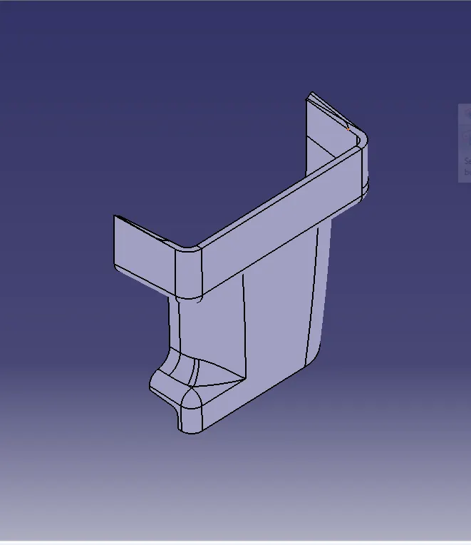
ISOMETRIC VIEW
FRONT VIEW
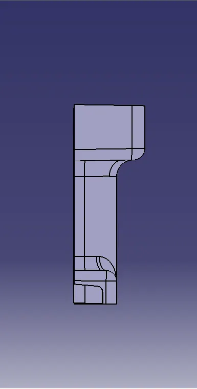
TOP VIEW
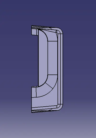
RIGHT VIEW
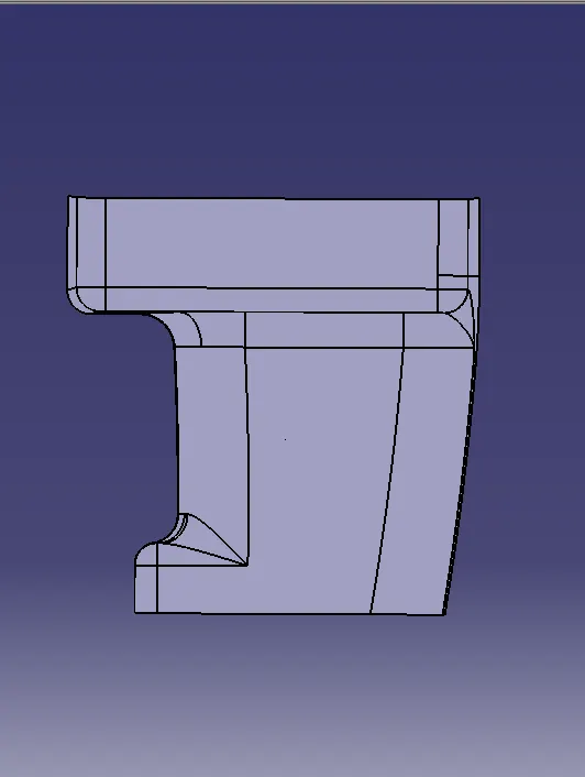
LEFT VIEW