Week 9 - Challenge 3 - Bumper
Procedure to make Bumper Part in CATIA V5:
At First the area has to be selected to form a Tooling Axis. In this Bumper part i have taken the center area to form a Tooling Axis because the center is easy to access the hole part. Then adding a point on the surface i have drawn a straight line along X Direction.
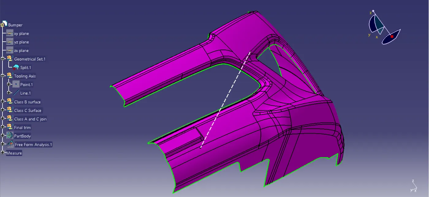
Fig 1. Bumper Tooling Axis
Now after the Tooling Axis is created the next operation is started which is forming a Class B surface. The Class B Surface is directly Offseted from Class A Surface with 3mm inside of Class A Surface. While doing Offset it have some missing surface that missing surface have to be created using some commands like Multiple Extract, Boundary, then Ectrapolate command to form the missing surface and then the Trim or Join command is used to combine or remove some surfaces.
The Command Icons are given below

Fig 2. Boundary, Extract and Multiple Extract Fig 3. Join , Trim
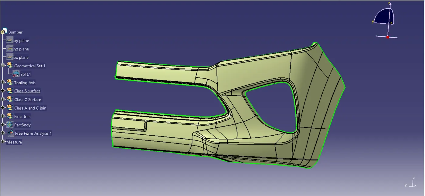
Fig 4. Bumper Class B surface
Then after the Class B Surface is Created the Class C Surface is started.
The Class C Surface is also takes a reference from Class A Surface but Class C Surface takes only Corner part of the Class A Surface because the Class C Surface is created to make a close surface Between Both Class A and B Surface. The Class C Surface is also created using Boundary, Extract, Trim and Join Command.
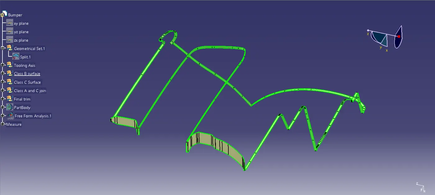
Fig 5. Bumper Class C surface
Then after the Class C surface is created both the Class A and C Surface is join.
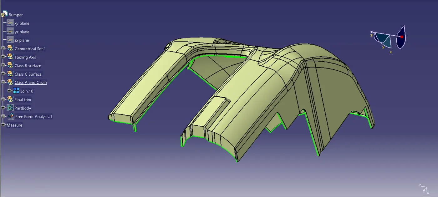
Fig 6. Class A and C Surface
Then after the Class A and C Surface is joined they where Trimed using Trim command with Class B Surface to form a closed Surface.
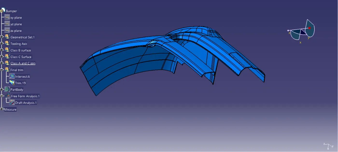
Fig 7. Bumper Final Surface
After the Closed Surface is created then it is formed a Solid Body using Close Surface Command in Part Work Bench.
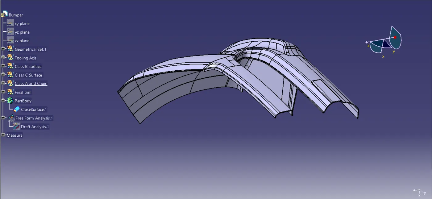
Fig 8. Close Surface Body
Then after making a Solid Body the Draft Analysis is done for the Solid Body.
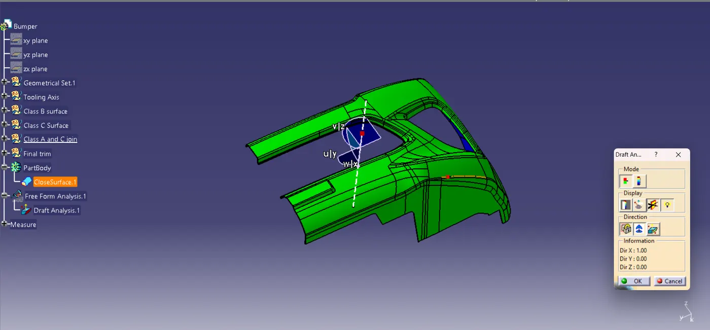
Fig 9. Bumper Draft Analysis