Week 7 Challenge - Assembly Workbench
Introduction:
In this course we learned about the Sketcher, Part Making, Boolean Operations, Drafting and Assembly in Workbench.
In these process we have used some common tools for our work, so lets look some of them. In Sketcher we have commonly used tools are Point, Lines, Plane, Circle, Arc, Axle, Rectangle, etc which are used from Profile toolbar. Then we use Constraint and Constraints Defined in Dialog Box which is use for making some commands like Coincidence, Concentricity, Parallel, Perpendicular, Equal, Horizontal, Vertical, Fix, Tangent, Distance, Lenght etc. These are the tools use in Sketcher Workbench.
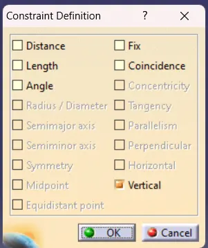
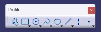
Fig:1 Constraint Definition Toolbar Fig:2 Profile Toolbar
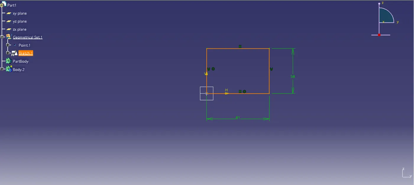
Fig:3 Simple Sketch
Then in Part Workbench we use Sketch-Based Feature Toolbar for making a Part or Cut body in the part. The Commonly used tools are Pad, Pocket, Shaft, Groove, Hole, Rib, Slot, Stiffener, etc.
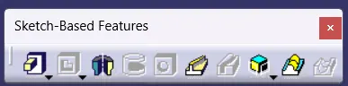
Fig:4 Sketch-Based Feature Toolbar
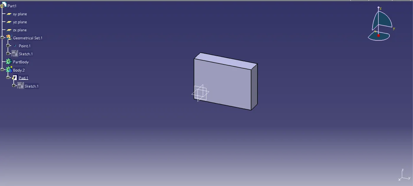
Fig:5 Simple Sketch Pad Part
Now we are going to use Boolean Operation which helps us in add, Remove, Union Trim, Assembly, Intersect, etc. to the main Partbody in the Feature Tree.
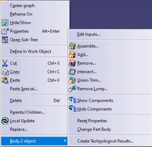
Fig:6 Boolean Option Toolbar
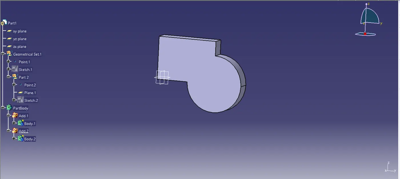
Fig:7 Simple Sketch Pad and added part
Now it is Drafting, in this area the Drawing of the Partbody was created for understanding the dimensions and also for the proper view of the image from the different section of the views where taken. The different section of views help in analysing the part and the sketch part in easy way. In Drafting also there are some tools which helps in dimensioning the area life Lenght, Angle, Radius, Diameter, Re-route Dimension, etc
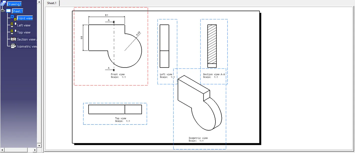
Fig:8 Drafting of Simple Sketch
Then the Final Part of the work is Assembly where all the parts are Combined to form a single part.
In this Assembly we will see the Quick Return Mechanism and CV Joint Parts where assembled.
First thing in the Assembly session are parts, the parts of the Quick Return Mechanism and CV Joint are drawn according to the required dimensions. The Part image are given below
- Quick Return Mechanism
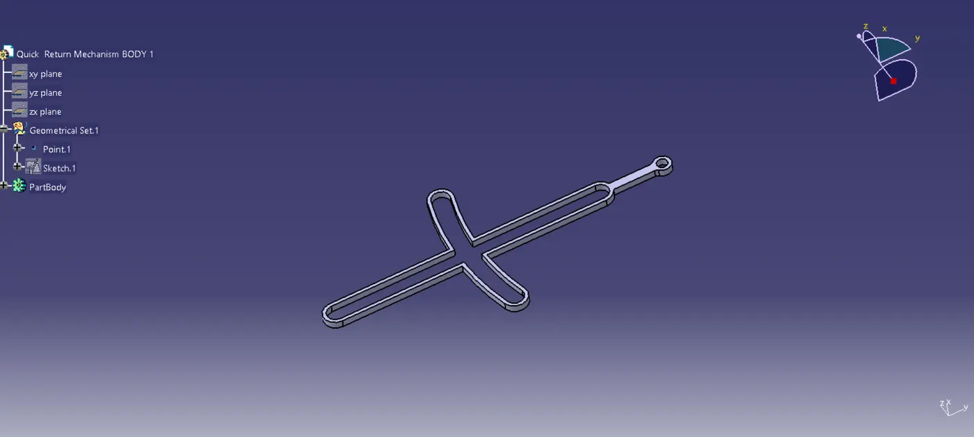
Fig:9 Quick Return Mechanism Body 1
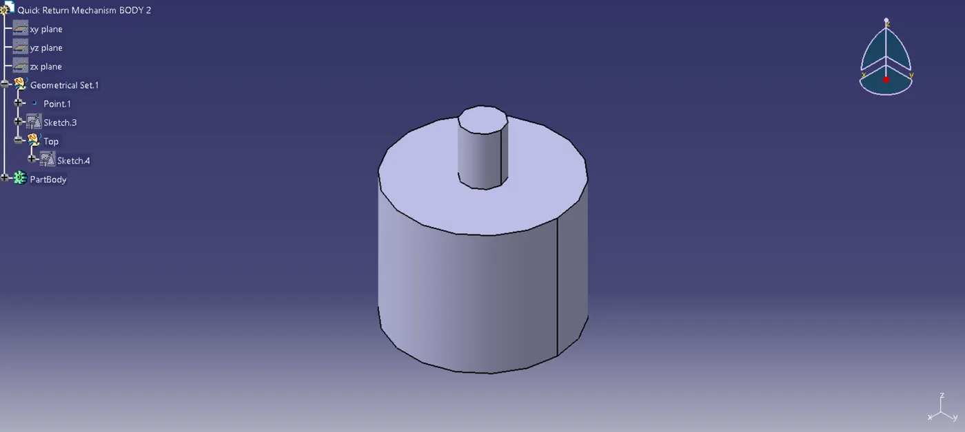
Fig:10 Quick Return Mechanism Body 2
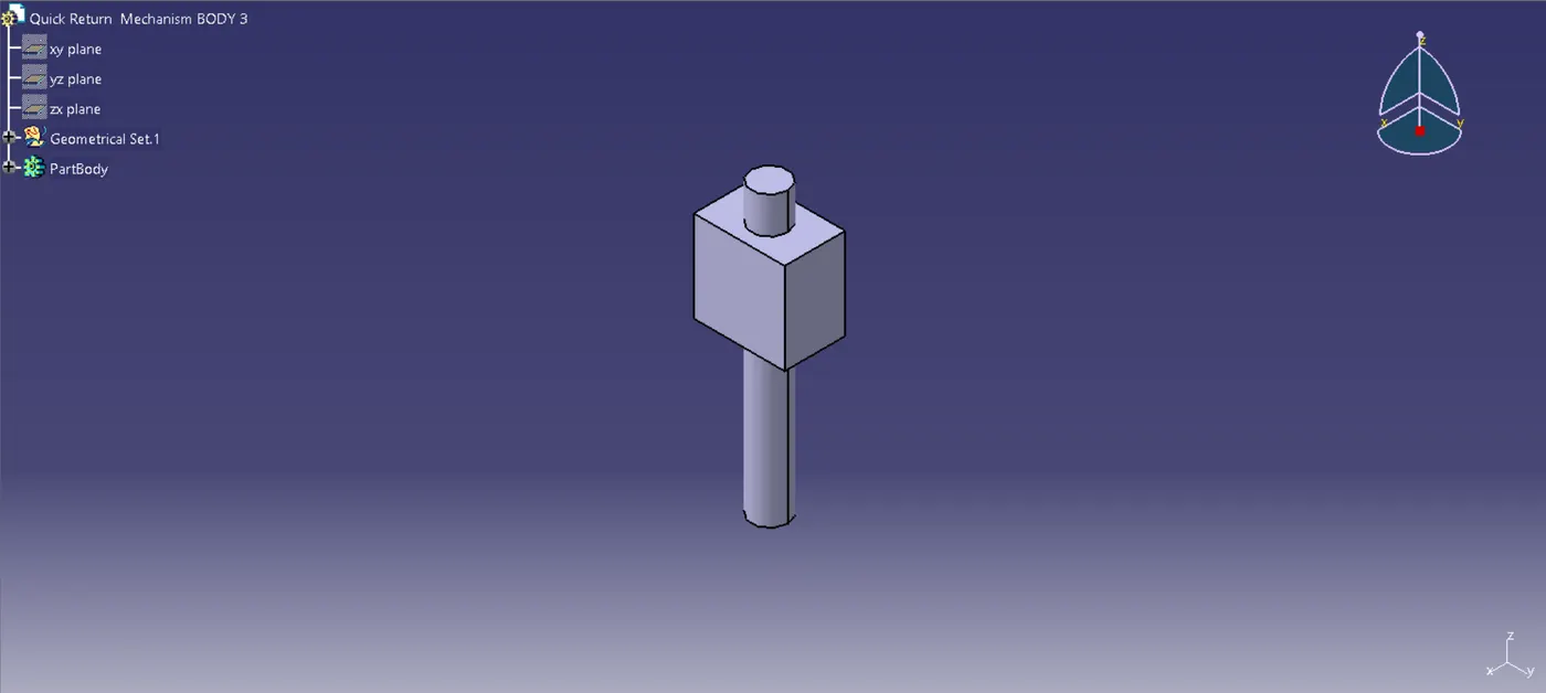
Fig:11 Quick Return Mechanism Body 3
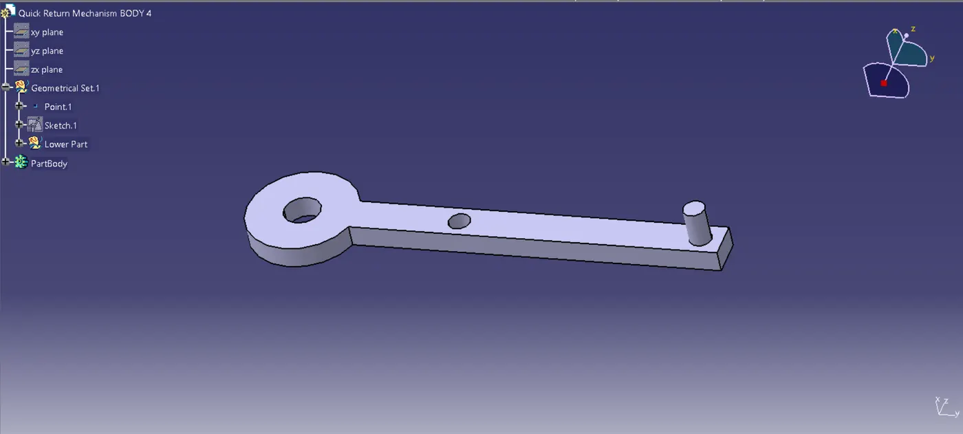
Fig:12 Quick Return Mechanism Body 4
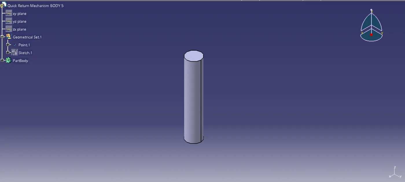
Fig:13 Quick Return Mechanism Body 5
2. CV Joint
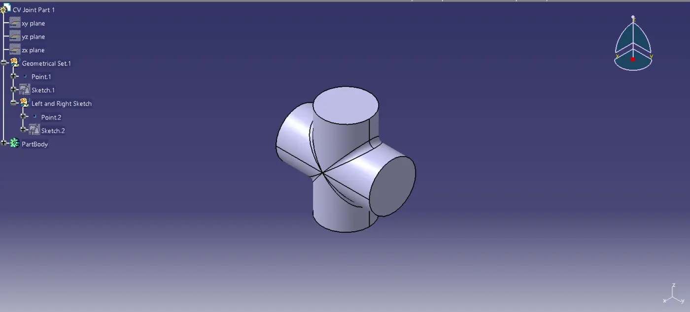
Fig:14 CV Joint Part 1
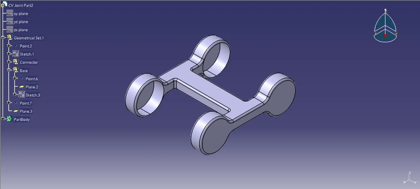
Fig:15 CV Joint Part 2
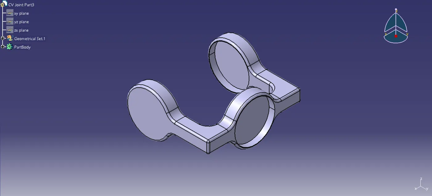
Fig:16 CV Joint Part 3
After the Parts are created they are graphic with some colour for a easy identification. These Graphic option can be found in the properties of the parts. Then they where join by the constrain like coincide by surface and drawing an imaginary Axis and coinciding. The image of both the Quick Return Mechanism and CV Joint's Assembly where given below
1. CV Joint Assembly
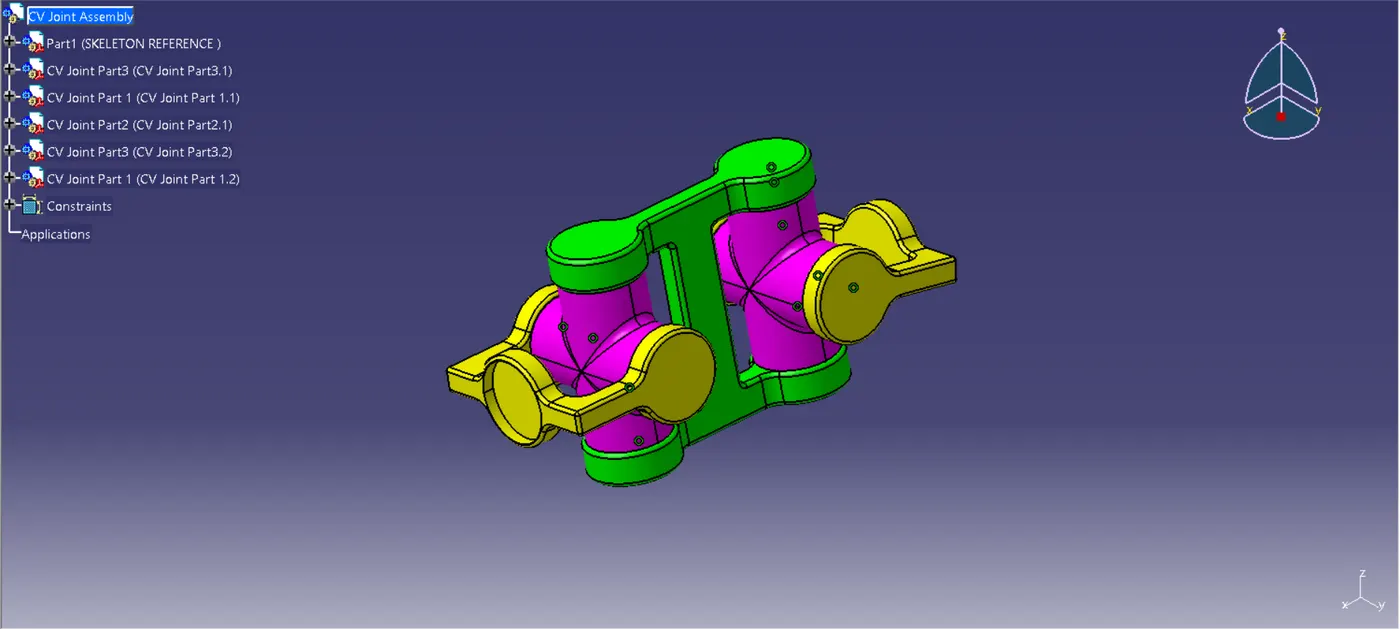
Fig:17 CV Joint Assembly Image
2.Quick Return Mechanism
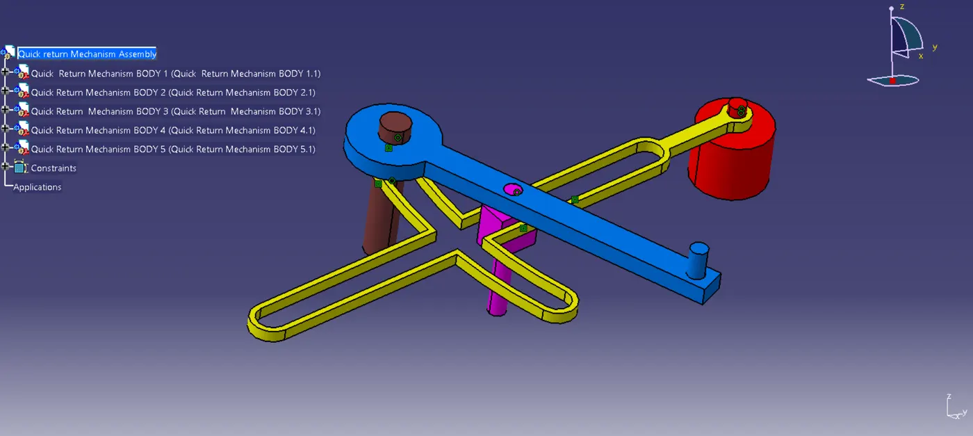
Fig:18 Quick Return Mechanism Assembly Image
After the Assembly the Drafting was done to take a 2D image of the Assembly with the required dimensions. The image of Drafting for both the CV joint and Quick Return Mechanism where given below
- CV Joint
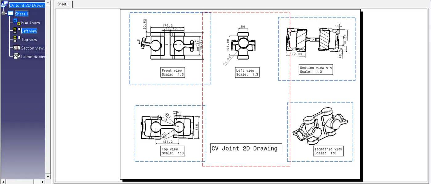
Fig:19 CV Joint 2D Drafting Image
2. Quick Return Mechanism
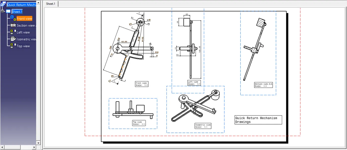
Fig:20 Quick Return Mechanism 2D Drafting Image