Week 9 - Challenge 2 - Switch Bezel Design
Procedure to do Switch Bezel using CATIA V5:
At first we need to check and analysis the product for any open surface. It can be checked by the Boundary Option. Then the Tooling Axis has to be drawn.
To draw the Tooling Axis we need to find a proper area which helps us to work easily on the product. In this work we have taken a base as a point to creat a dummy tooling axis system(along Z Direction). Then from the point a Sketch is created along YZ directions. Now the Intersection was taken and then from the two opposite lines the Bisecting line is created. 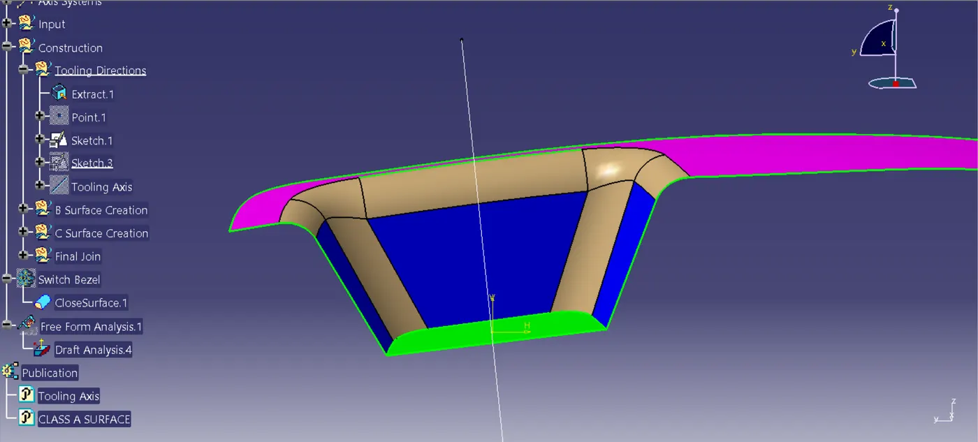
Fig 1. Sketch 1 Bisecting Line
Now a Sketch 2 is created to form another line for Tooling Axis. This line have a value of 5 degree.
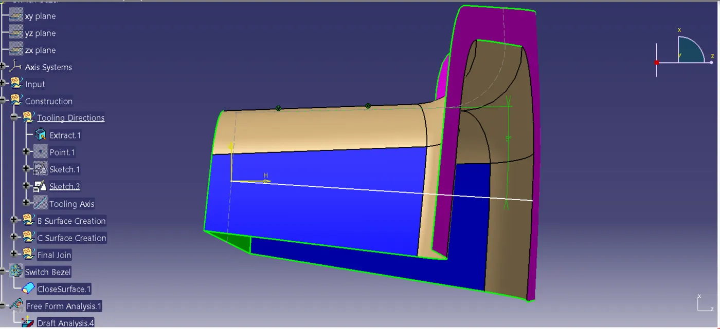
Fig 2. Sketch 2 Bisecting Line
Now with the help of both the lines the Tooling Axis is created.
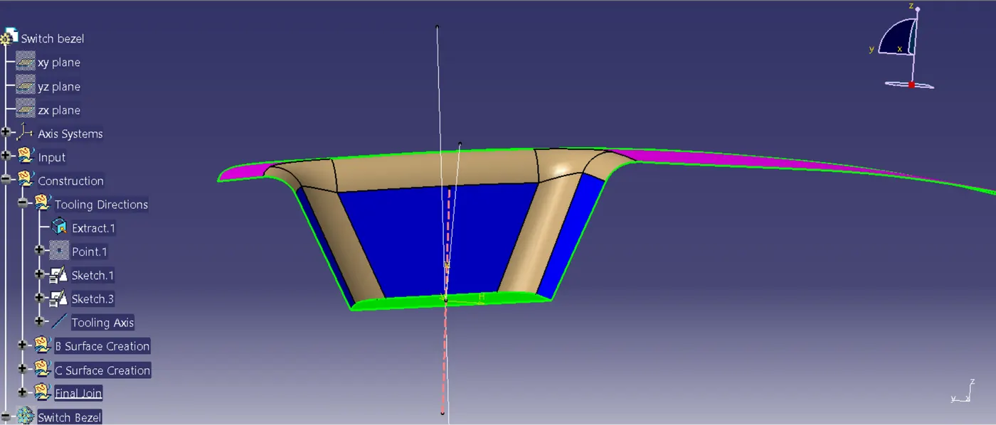
Fig 3. Switch Bezel Tooling Axis
Then after the Tooling Axis is created the Tooling Axis and the Class A Surface both are Publication for an easy access.

Fig 4. Publication
Then after the publication is done. The B Surface and the C Surface where created in Geometrical Set.
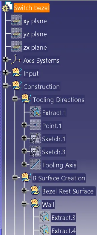
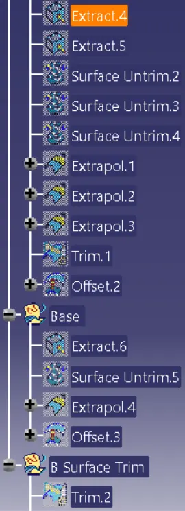
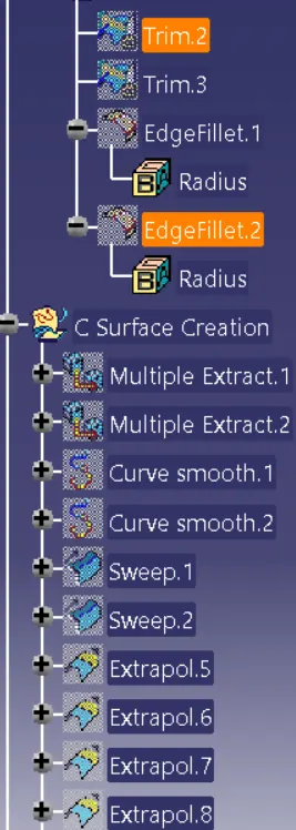
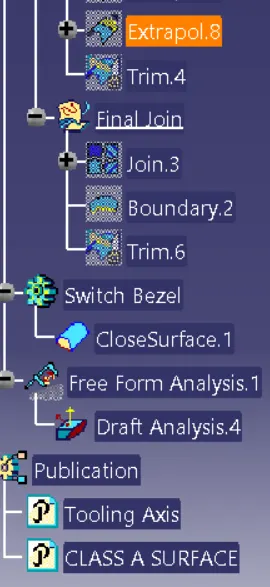
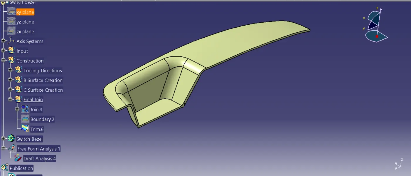
Fig 5. Final Surface Output
Then the Close Surface feature is used to make a Solid Body from the Surface.
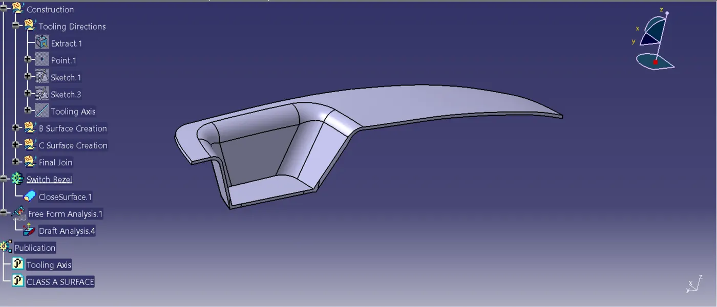
Fig 6. Closed Solid Body
After the Closed Solid Body is done the Analysis part is started. In Analysis Toolbar the Draft Analysis Command is selected. Then in the Customize Toolbar the material mode is selected. Then the Compass is selected and place it in the Tooling Axis and lock the direction. Then Select the Analysis under the running point to check the value of the Solid Body.

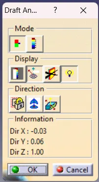
Fig 7. Customize Toolbar Fig 8. Draft Analysis Toolbar