Week 9 - Challenge 1 - Base Bracket Design
Procedure to make Base bracket in CATIA V5:
At First we need to check and analysis the product for any open surface. It can be checked by the Boundary Option. The the Tooling Axis has to be Drawn.
To Draw the Tooling Axis we need to find a proper area which help us to work easily on the product. In this work we have taken a hole in the top position of the surface to draw our Dummy Tooling Axis System (along Z Direction).Then in that hole we make a center point and then draw a line in a Z direction. Then make a center point in the hole and place a YZ Plane. Now with the plane do a intersection on a Class A Surface. Now take the inner edge on the intersection line and make a bisection. Now the Tooling Axis is created.
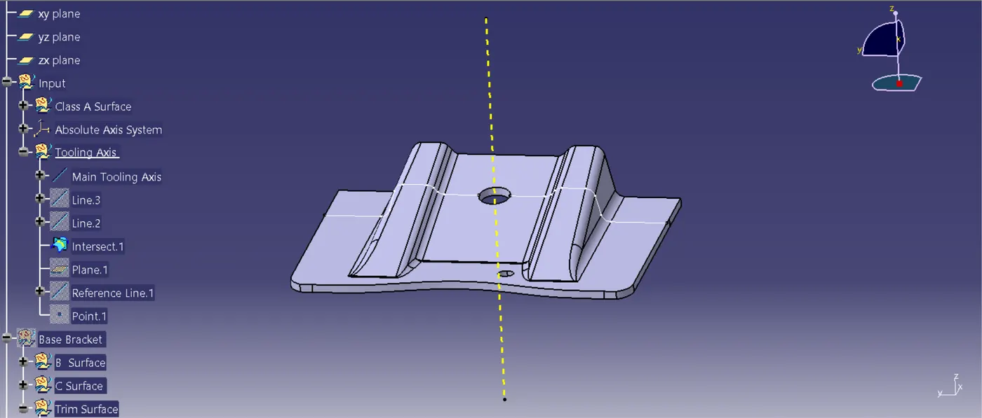
Fig 1. Base Bracket Tooling Axis
Now its time for a Draft Analysis to analysis the Class A Surface. In this first we need to change the part to the Material option in the Customize View Parameters.

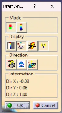
Fig 2. Customize Toolbar Fig 3. Draft Analysis Toolbar
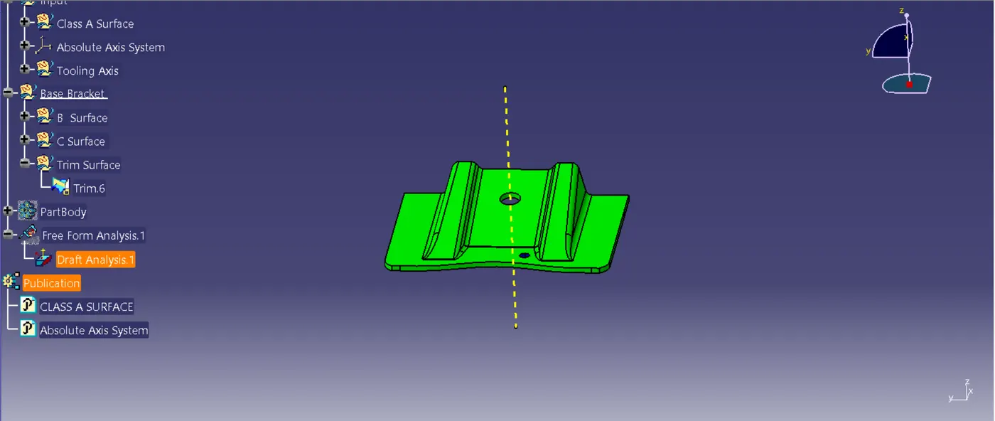
Fig 4. Base Bracket Draft Analysis
Then after the Draft Analysis is completed the work of a surface were created in a Geometrical Set with the reference of Class A Surface. Their Feature Trees are given below.
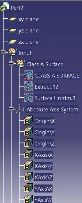
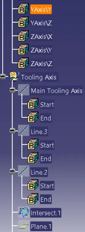
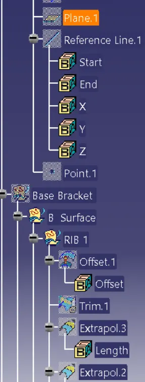
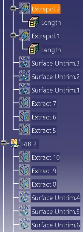
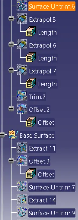
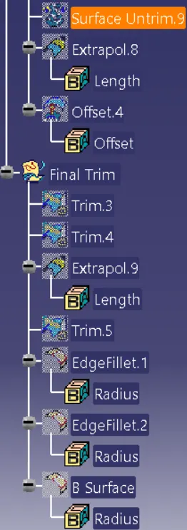
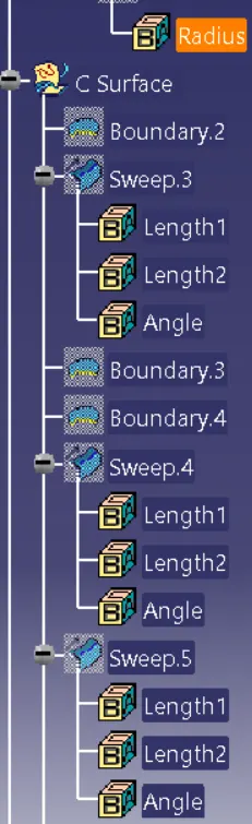
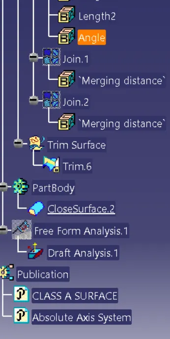
Then after the Class B Surface and Class C Surface is created the Final Trim with both the surface give the Final Surface Output. In the Final Output Blue color is given to the Surface.
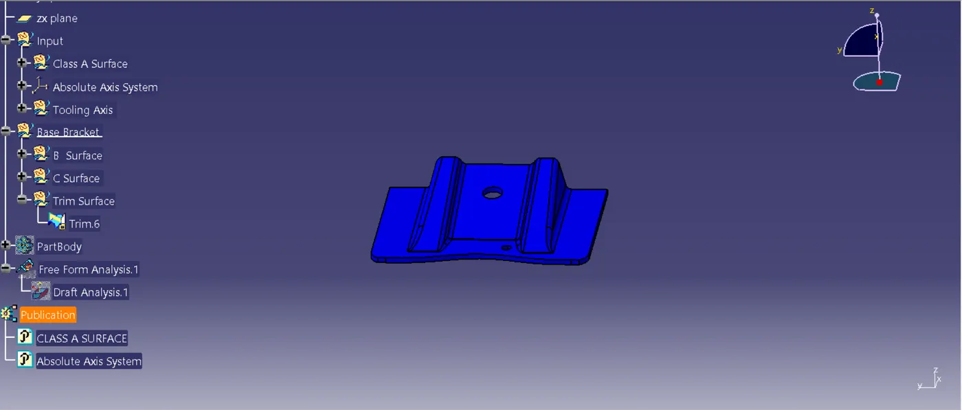
Fig 4. Base Bracket Final Output Surface
After the Surface is done the Close Body is made out of it in the part section.
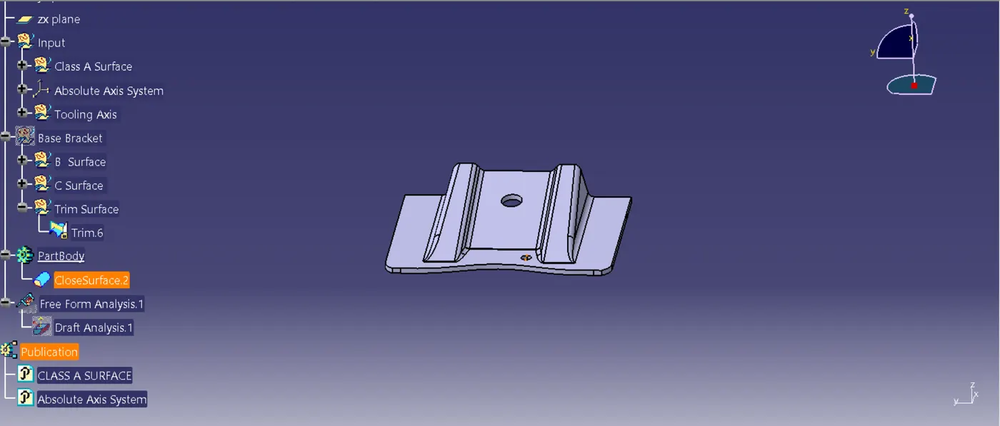
Fig 5. Base Bracket Closed Body