Week 9 - Challenge 3 - Bumper
Dear sir,
Please check the attached file named Bumper (Lohit Tripathy).CATPart. The file creation process is described below.
Bumper
First I have opened BUMPER CAT PART provided for the challange, then saved it as .CATPart file in which Class A surface was pre existed and created B & C surfaces, tooling axis, created a closed surface by using them, then converted it into a solid body and did the draft analysis.
- First I renamed the initia geometrical set as "Input" under which "Provided Class A" and " Tooling axis" Geometrical sets are present. Class A surface is available under "Provided Class A" and under "Tooling axis" I created tooling axis.
Tooling axis creation
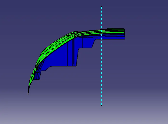
- For this component I have gone through a different approach than bisecting method. First I was looking for the view from which I can see most of the surfaces of Class A, then I got my desired view from normal view of YZ plane.
- Then I placed a point named "Ref. Point" and created a line by using point and direction method in X axis direction.
- Change the color, thickness and type of the line and here it is the tooling axis of the part.
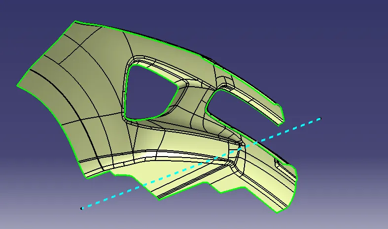
(The blue dotted line is the tooling axis)
Class B, C, closed surface and the solid body creation
- After creating the tooling axis I created the Class B surface by a different approach then the earlier projects because of the surface complexity of the bumper.
- First I applied offset command as same as the component thickness on Class A towards required direction, then created the missing parts of that offset by using several commands like multiple extract, boundary, extrapolation etc.
- After that created the Class C surface and extended the Class B surface where ever needed, so that the Class B & C will be completely closed.
- Then join the Class A and C surface, then trimmed Class B surface with the join surface and then the closed surface of the bumper is created.
- Then converted the closed surface into a solid body by using close surface command in part workbench and then performed the draft analysis.
Draft analysis of the solid body
- For draft analysis I clicked on " Customize view parameters" on view mode & selected "Material", then go to Insert > Analysis > Feature draft analysis.
- The default analysis mode is Quick Analysis Mode. In this more only three options are there just like the below image, any angle above 3 deg. will be green, any angle above 0 to 3 deg. will be Red and any angle less than 0 will be Blue. You can set the limits for the angles by double clicking on them. The ideal draft angle of any component is 3 deg. but here I have change the required draft angle to 2.5 deg. from 3 deg., because the draft of this component doesn't satisfy above 2.5 deg. Once you select on any surface of the solid body, as per the angles the surface colours will be changed. Here colour of all the surfaces with more than 2.5 deg. draft angle has changed to green and color of all the surfaces with less then zero deg. draft angle has changed to blue.
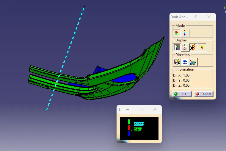
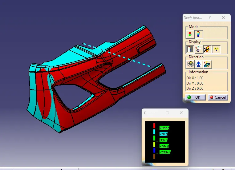
- Once I switched to Full analysis mode I can check the draft angle in more detail. In this mode there are so many options are there just like the below image, any angle above 20 deg. Will be Red, any angle in between 2 to 20 deg, will be Cyan, any angle in between 0 to 2 deg. will be Green, any angle in between -2 to 0 deg. will be Yellow, any angle between -20 to -2 deg. will be Navy blue and any angle less than-20 deg. will be Brown. Once I selected any surface the color of the component surfaces has changed as per the drafting angle.
- In display section first option is Colour Scale option, which changes the surface colours as per their draft angles. 2nd option is Analysis under the running point. In this option draft angle can be checked at any point. You can see the below image it is showing 22.227 deg. on that point after selecting that option. Rest 2 options are for changing the light effect on the part while draft analysis.
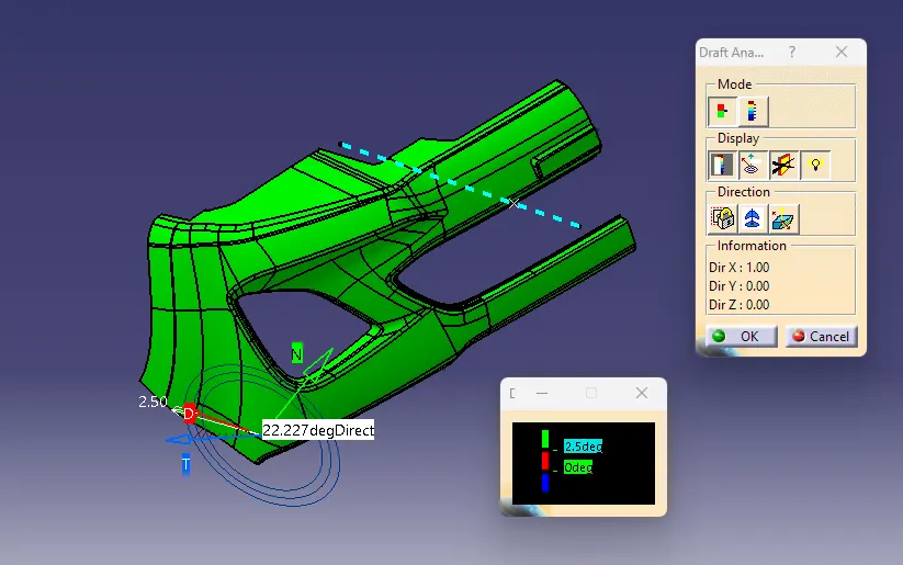
- In direction section first option is for locking or unlocking the draft direction. 2nd option is Compass option for defining draft direction, which is shown in the below picture. 3rd option is inverses the draft direction.
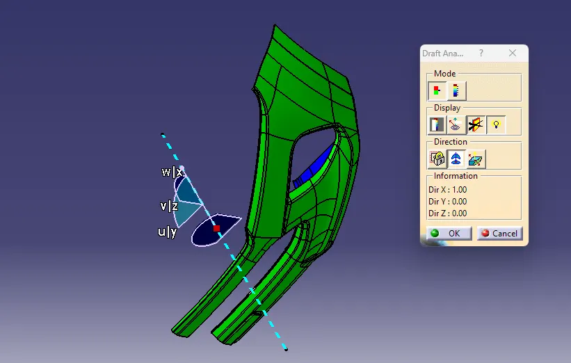
- Basically while analyzing the draft angle, 1st on the view mode I selected the customize view parameters & then selected material on the next dialog box. Then brought the compass near the tooling axis and aligned with it. Check the angles with color scale option and also check the angles by analysis under the running point option.
- Same way I perform the draft analysis of Class A & the colour scale images of the solid body in various orientations are attached below.
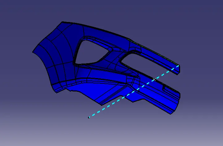
Isometric view
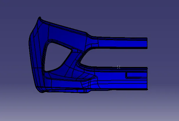
Front view
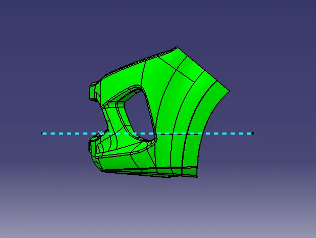
Side view
Top view
Thanks & regards
Lohit Tripathy