Week 9 - Challenge 1 - Base Bracket Design
Dear sir,
Please find the attached CATPart file & the report of the CATPart file creation is given below.
Base Bracket Design Report
First I have opened BASE BRACKET STEP FILE provided for the challange, then saved it as .CATPart file in which class A surface was pre-existed & created class B & C surfaces, tooling axis & did the draft analysis.
- I renamed the 1st geometrical set as "Input" Under which "Class A Surface" & "Tooling Axis" geometrical sets are present. Class A surface is available under "Class A Surface" and under "Tooling Axis" I created the tooling axis.
-
Tooling Axis Creation
- Created "Ref. Point" by taking the center of the hole present in middle of the ribs of class A surface & created "Intersecting Axis System" on that point.
- Inserted "Plane.1" along X-Y axis of the "Intersecting Axis System", then applied intersection command by taking the first element as class A surface & second element as "Plane.1".
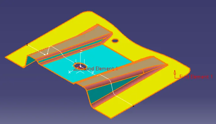

- Then created "Line.1" & "Line.2" on the intersection curve as shown in the below drawing.
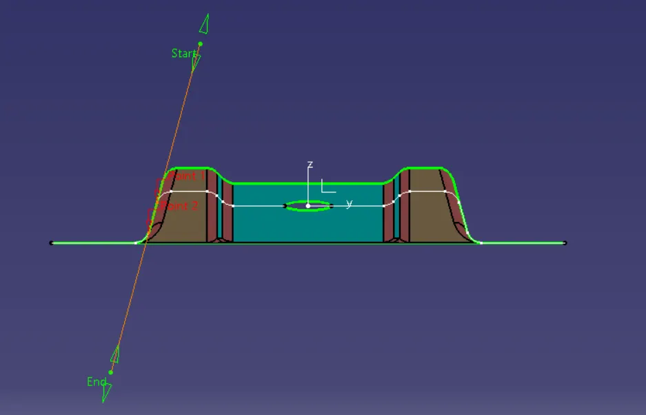
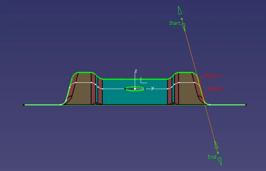
- After that again I went to line command & selected the line type as "Bisecting", also selected "Ref. Point" as bisecting point. Created the line on the "Ref. Point" in between "Line.1" & "Line.2" by selecting both of them and renamed it as "Tooling Axis". This is how I created tooling axis by Bisecting Method.
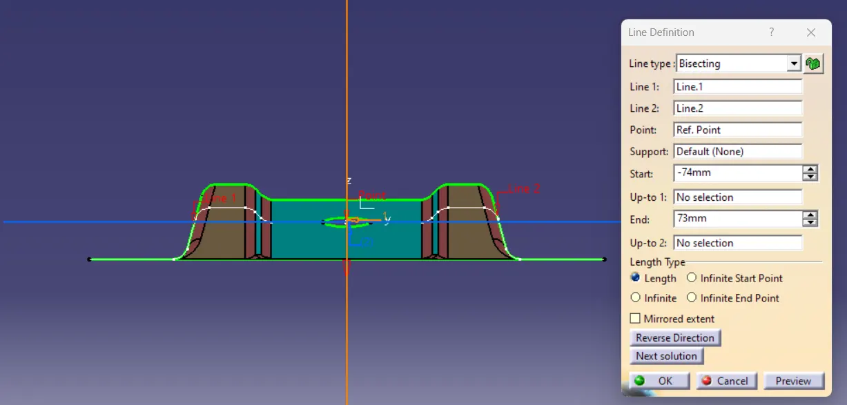
- After creating the tooling axis, I did the draft analysis of the class A surface.
-
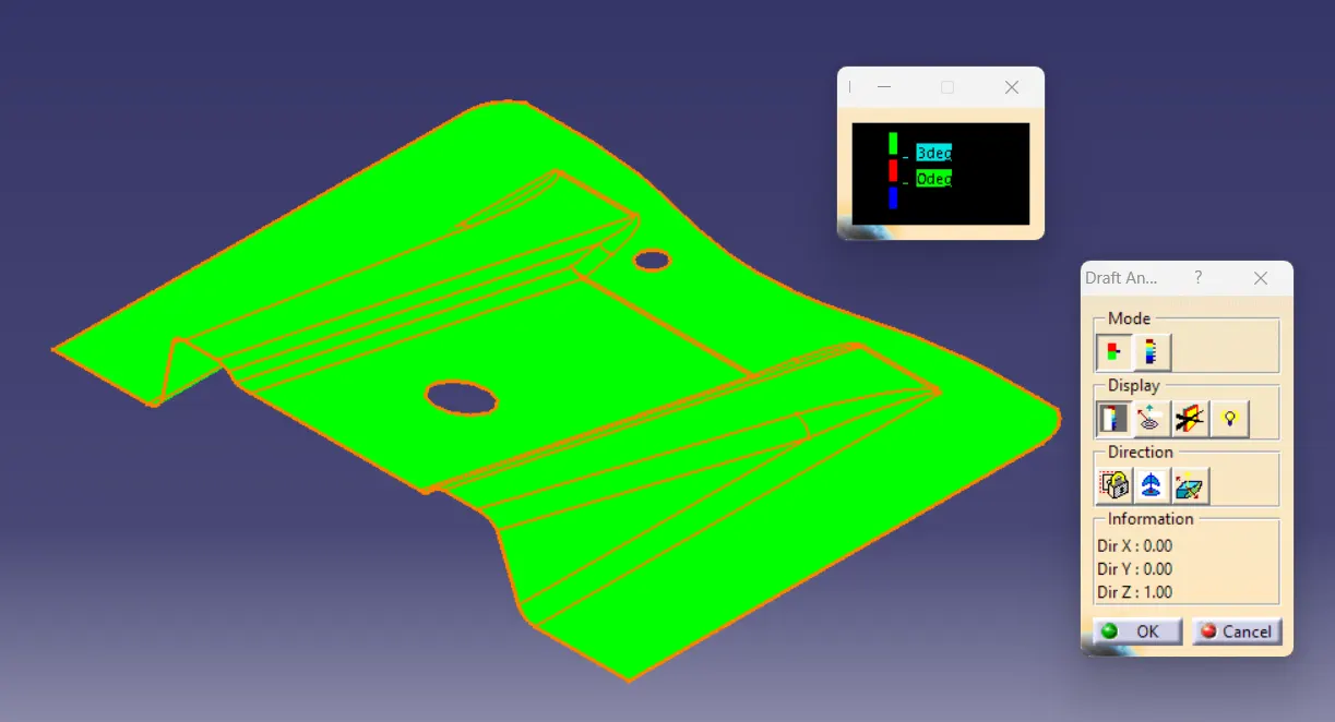
- For draft analysis I clicked in "Customize View Parameters" on view mode & select "Material", then go to Insert > Analysis > Feature Draft Analysis.
- The default analysis mode is Quick Analysis Mode. In this mode only 3 options are there just like the below image, any angle above 3 deg. will be green, any angle in between 0 to 3 deg. will be Red and any angle less than 0 will be Blue. You can set the limits of the angles by double clicking on them. Once you select on any place of the class A surface as per the angles the colours of the places will be changed. Here all the angles are more than 3 deg. so whole surface is green. The standard minimum draft angle is 3 deg. so I was checking by every angle with respect to 3 deg.
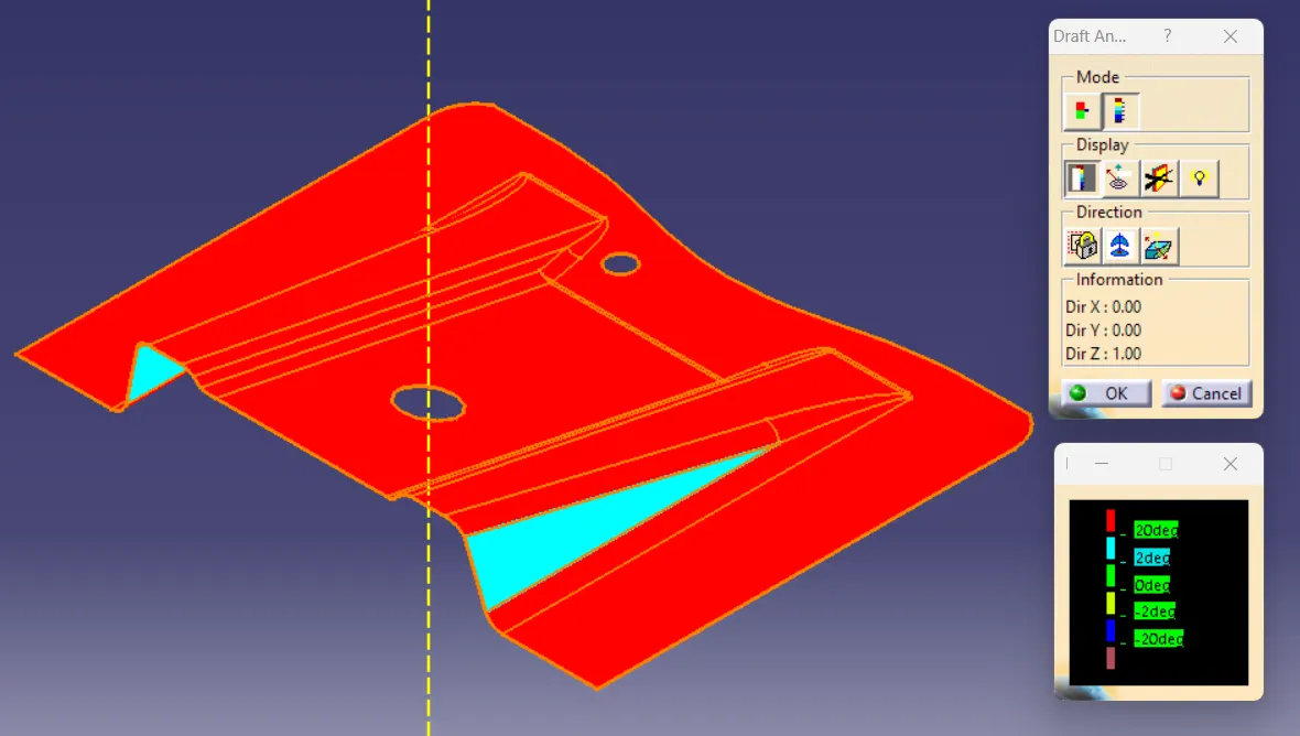
- Once I switched to Full analysis mode I can check the draft angle in more detail. In this mode only so many options are there just like the below image, any angle above 20 deg. will be Red, any angle in between 2 to 20 deg. will be Cyan, any angle in between 0 to 2 deg. will be Green, any angle in between -2 to 0 deg. will be Yellow, any angle in between -20 to -2 deg. will be Navy Blue and any angle less than -20 will be Brown. You can set the limits of the angles by double clicking on them. Once you select on any place of the class A surface as per the angles the colours of the places will be changed. Here all the places with angles more than 20 deg. are Red & places with angles in between 2 to 20 deg. are Cyan. This mode is specially used for the complex surfaces.
- Draft analysis of class A surface

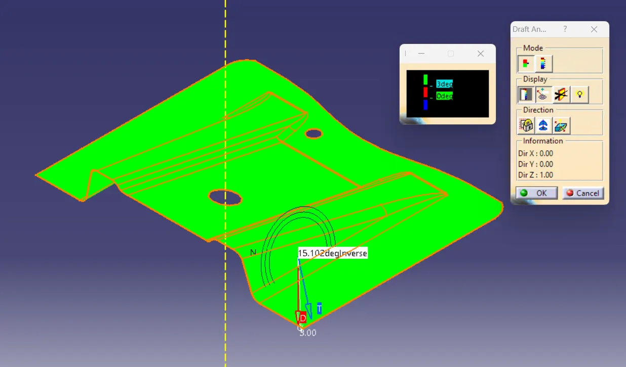
- In display section 1st option is Color Scale option, which surface colors will be change as per the draft angles. 2nd option is Analysis under the running point. In this option can check the draft at any point. You can see the below image it is showing 15.102 deg. on that point after selecting that option. Rest 2 options are not much useful.
- in direction section 1st option is for locking or unlocking the draft direction. 2nd option is compass option for defining draft direction, which is shown in below picture. 3rd option inverses the draft direction.
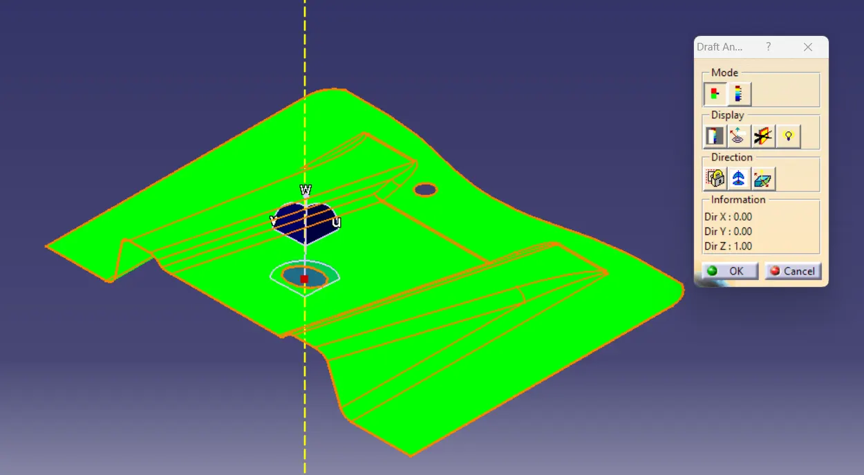
- Basically while analysing the draft angle of class A suface, 1st on the view mode I selected the customize view parameters & then selected material on the next dialog box. Then brought the compass near the tooling axis and alighned with it. Checked the angles with color scale option and also checked the angle by analysis under the runnung point option.
-
Draft Analysis of Final Plastic component/Solid body
- I did the draft analysis of the solid body same way I did the class A surface. The color scale images of the solid body in various orientations are attached.
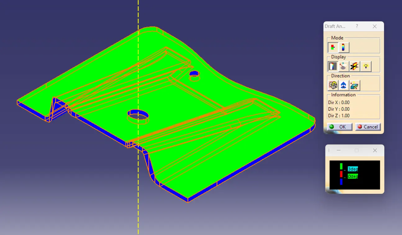
Isometric View
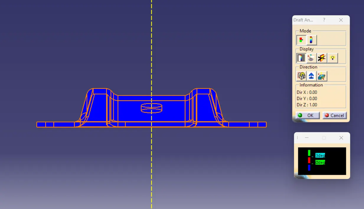
Front View
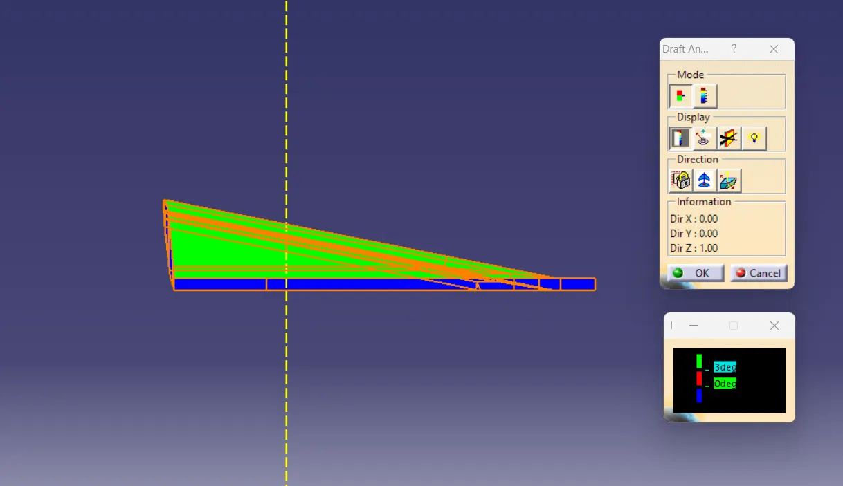
Side View
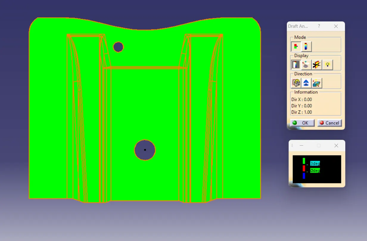
Top View
Thanks & Regards
Lohit Tripathy