Week 7 Challenge - Assembly Workbench
Dear sir,
Please find the attached zip file, which contains part files (.CATPart), assembly files (.CATProduct), drafting files (.CATDrawing & .PDF) & snaps of the CAD files in the specified folder as per the given assignment. The procedure followed to complete the assignment mentioned below.
-
Quick Return Motion Mechanism(Assignment - 1)
-
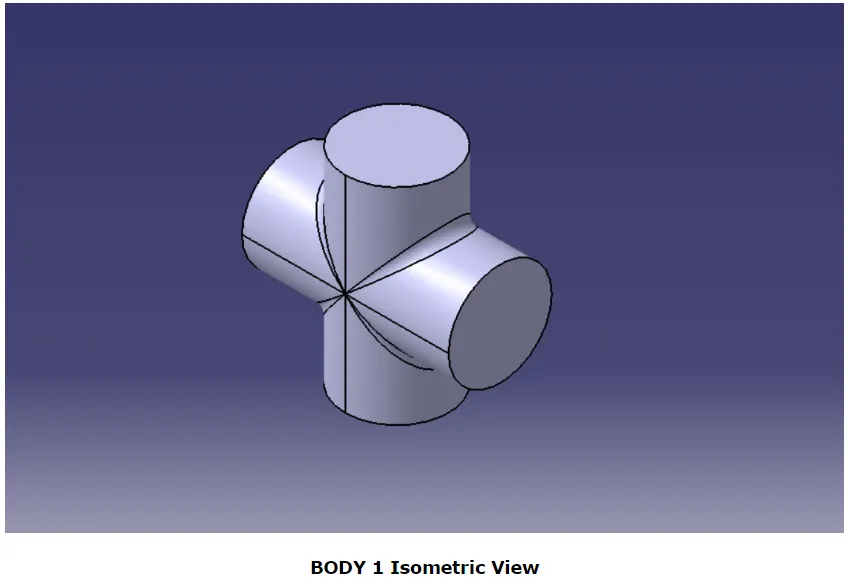
BODY 1.CATPart
- Created a part file named as "BODY 1" & created the reference point for the part named as "Ref. Point" in the coordinate of X=0mm, Y=0mm & Z=0mm.
- Then created a geometrical set named as "Linear Guide Profile" under the 1st geometrical set named "Geometries" & made the "Sketch.1" under "Linear Guide Profile".
- Changed the name of the main body to "Movement Guide" under which created a pad named "Linear Guide" followed by "Sketch.1".
- Then created "Curved Guide Profile" a geometrical set by taking parent as "Geometries" and under that created "Sketch.2".
- Inserted a new body with the name "Curved Body" under which I made "Pad.2" followed by "Sketch.2" & used union trim command to join with the existing body & to remove the unnecessary surfaces.
- Sketched "Sketch.3" by taking "Extension Profile" as a parent under "Geometries".
- Created "Pad.3" by following "Sketch.3" under a new body named as "Extension". Then used the union trim command.
- Then created "Extension Slot Profile" a geometrical set by taking parent as "Geometries" and under that created "Sketch.4".
- Inserted a new body with the name "Extension Slot" under which I made "Pad.4" followed by "Sketch.4" & again used the union trim command.
- At last applied fillet on the necesssry edges. Follow the below pictue to see how "BODY 1" looks like.
- While assembly process some points & axis for reference has to be inserted & after inseting I published the important element for the assembly. Published elements are: xy plane, yz plane, zx plane, Ref. Point,Axis.1, Axis.2, Axis.3, Point.2, Point.3 & Line.1.
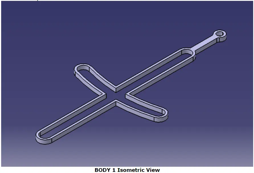
-
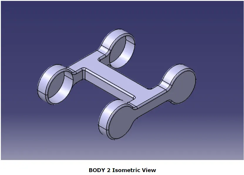
BODY 2.CATPart
- Created a part file named as "BODY 2" & created the reference point for the part named as "Ref. Point" in the coordinate of X=0mm, Y=0mm & Z=0mm.
- Then created a geometrical set named as "Base Profile" under the 1st geometrical set named "Geometries" & made the "Sketch.1" under "Base Profile".
- Changed the name of the main body to "Body 2" under which created a pad followed by "Sketch.1".
- Then created "Extension Profile" a geometrical set by taking parent as "Geometries" and under that created "Sketch.2".
- Inserted a new body with the name "Extension" under which I made "Pad.2" followed by "Sketch.2" & used add boolean command to join with the existing body.
- While assembly process one axis for reference has to be inserted & after inseting I published the important element for the assembly. Published elements are: xy plane, yz plane, zx plane, Ref. Point,Axis.1. The pictue of "BODY 2" mentioned below.
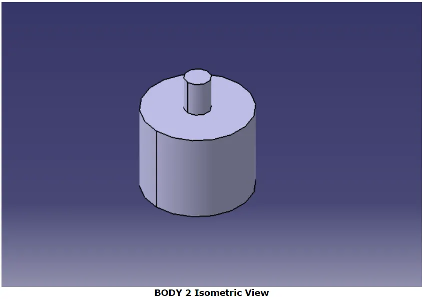
-
BODY 3.CATPart
- Created a part file named as "BODY 3" & created the reference point for the part named as "Ref. Point" in the coordinate of X=0mm, Y=0mm & Z=0mm.
- Then created a geometrical set named as "Block Profile" under the 1st geometrical set named "Geometries" & made the "Sketch.1" under "Block Profile".
- Changed the name of the main body to "Linear Movement Link" under which created a pad named "Linear Block" followed by "Sketch.1".
- Then created "Pin Profile" a geometrical set by taking parent as "Geometries" and under that created "Sketch.2".
- Inserted a new body with the name "Pin" under which I made "Pad.2" followed by "Sketch.2" & used add command.
- While assembly process some axis for reference has to be inserted & after inseting I published the important element for the assembly. Published elements are: xy plane, yz plane, zx plane, Ref. Point,Axis.1, Axis.2. The pictue of "BODY 3" mentioned below.
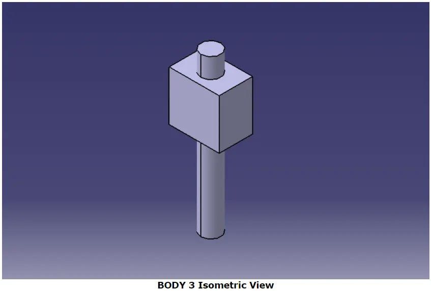
-
BODY 4.CATPart
- Created a part file named as "BODY 4" & created the reference point for the part named as "Ref. Point" in the coordinate of X=0mm, Y=0mm & Z=0mm.
- Then created a geometrical set named as "Base Profile" under the 1st geometrical set named "Geometries" & made the "Sketch.1" under "Base Profile".
- Changed the name of the main body to "Motion Arm" under which created a pad named "Base" followed by "Sketch.1".
- Then created "Slot Profile" a geometrical set by taking parent as "Geometries" and under that created "Sketch.2".
- Inserted a new body with the name "Slot" under which I made "Pad.2" followed by "Sketch.2" & used remove command to remove material for the slots.
- Sketched "Sketch.3" by taking "Lever Profile" as a parent under "Geometries".
- Created "Pad.3" by following "Sketch.3" under a new body named as "Lever". Then used the add command.
- While assembly process some axis for reference has to be inserted & after inseting I published the important element for the assembly. Published elements are: xy plane, yz plane, zx plane, Ref. Point,Axis.1, Axis.2. The pictue of "BODY 4" mentioned below.
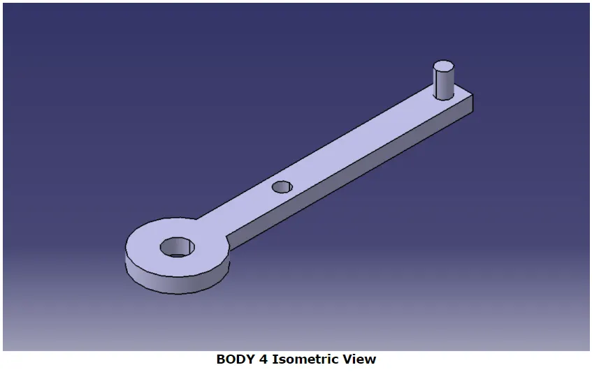
-
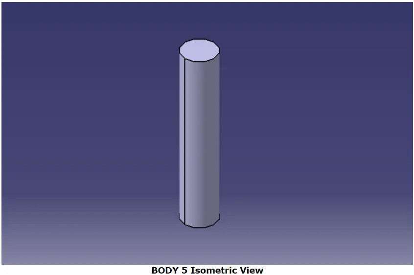
BODY 5.CATPart
- Created a part file named as "BODY 5" & created the reference point for the part named as "Ref. Point" in the coordinate of X=0mm, Y=0mm & Z=0mm.
- Then created a geometrical set named as "Link Profile" under the 1st geometrical set named "Geometries" & made the "Sketch.1" under "Link Profile".
- Changed the name of the main body to "Curved Guide Link" under which created a pad followed by "Sketch.1".
- While assembly process one axis for reference has to be inserted & after inseting I published the important element for the assembly. Published elements are: xy plane, yz plane, zx plane, Ref. Point,Axis.1. The pictue of "BODY 5" mentioned below.
-
Quick Return Motion Mechanism Assembly
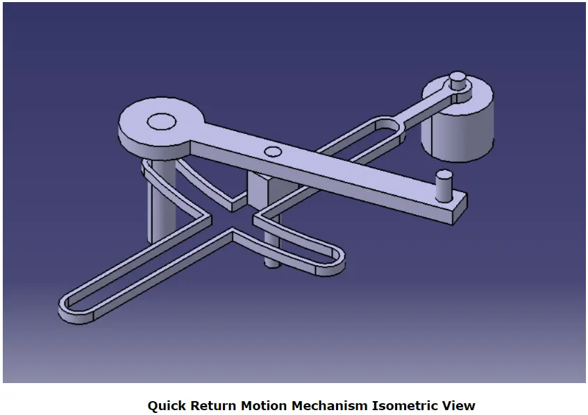
- Created a product file named "Quick Return Motion Mechanism" & add the created above parts files.
- Then added a new part. While adding it asked whether to define separate origin point for the part or define the same origin as the assembly, I clicked yes to define separate origin point for that part.
- Renamed the new Part as "Skeleton Reference" and by using graph tree reordering I took "Skeleton Reference" to the top & made it as the 1st child pard of "Quick Return Motion Assembly".
- By double clicking on the part file in the graph tree I activated the part workbench for the specified file and added the lines, points and the axis needed in part files to align the parts as needed for assembly.
- Also created a point named "Asm. Ref. Point" with X,Y & Z as 0mm. I used this point as the origin of the assembly after fixing this.
- Then I fixed "Skeleton Reference" by applying fix component command and by the reference of it I placed all other parts accordingly.
- 1st fixed "BODY 1" with the origin of the assembly by applying Coincidence Constraint on the ref. points and 1 horizontal & 1 vertical plane of Skeleton Reference & BODY 1.
- Then I placed BODY 2 with BODY 1 by aligning Extension Slot Axis of BODY 1 and Extension Axis of BODY 2, for which I used Coincidence Constraint and also Contact Constraint on the meeting surfaces of BODY 1 & BODY 2.
- For placing the BODY 3 I applied Coincidence Constraint on the Ref. Point of the part & Linear Guide way Line of BODY 1 & applied Contact Constraint on the meeting surfaces of BODY 1 & BODY 3.
- Then I aligned BODY 4 by appling Coincidence Constraint on the near to the centre Slot Axis of BODY 4 and Pin Axis of BODY 3 & applied Contact Constraint on the meeting surfaces of BODY3 & BODY 4.
- For aligning the other slot I used Manupulation command. Clicked on drag around any axis, then selected aligned Slot Axis with the Pin Axis and turned the part till other Slot Axis approximately aligned with the Curved Guide Axis of BODY 1.
- Then applied Coincidence Constraint on the Slot Axis, Curved Guide Axis and the Axis of BODY 5.
- Then applied Contact Constraint on the meeting surfaces of BODY 4 & BODY 5. Now the assembly is done. Follow the below pictue to see how "BODY 1" looks like.
-
Quick Return Motion Mechanism Drafting
- Created New Drawing file and 1st added isometric view of the assembly and pointed out the parts in Sheet Background.
- Created the Title Block with the drawing details in Sheet Background.
- Placed the Front View & Projection View of the assembled parts in the next sheets in sequence and provided the Annotations on the drawings.
-
-
CV joint(Assignment - 2)
- Created the parts and assembly of CV Joint same as assignment - 1 only the figues, dimentions and constants are not same. Have applied as per the requirements. Please find the Isometric Views of the Parts and the assembly below.
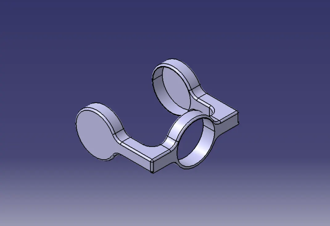
BODY 3 Isometric View
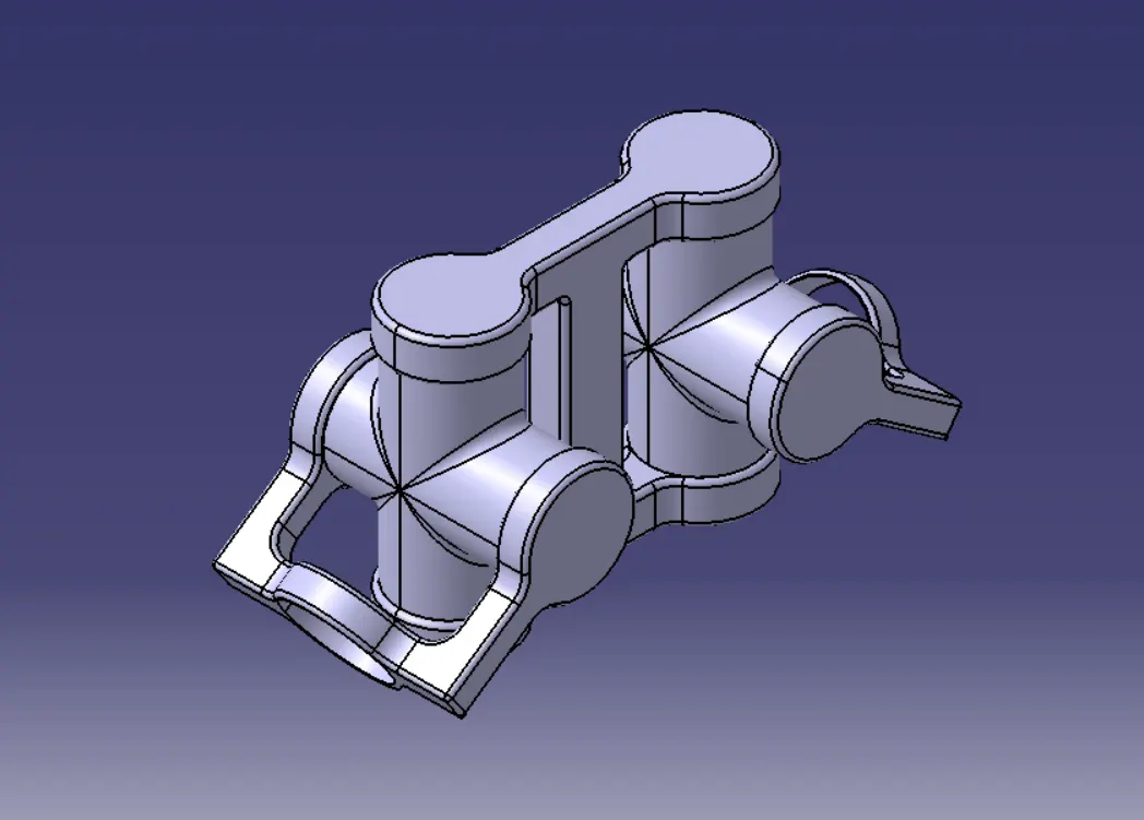
CV Joint Isometric View
Thanks & Regards
Lohit Tripathy