Week 10 - Challenge 2- Attachment Feature Creation (Dog House)
Dear sir,
Please cheque the attached file named Door Trim - Dog House (Lohit Tripathy).CATPart. The file creation process is described below.
Door Trim - Dog House
First I opened DOOR TRIM STEP FOR DOG HOUSE provided for the challenge, saved it as .CATPart file in which I used provided Class A surface to Create Class B & C surface, tooling axis, created a closed surface by using them, then converted it into a solid body, then crated created the required ribs & screw bosses, at last performed the draft analysis.
- I renamed the initial geometrical set as "Input" under which "Provided Class A" and "Tooling axis" geometrical sets are present. Class A surface is available under "Provided Class A" and under "Tooling axis" I created the tooling axis.
-
Tooling axis Creation
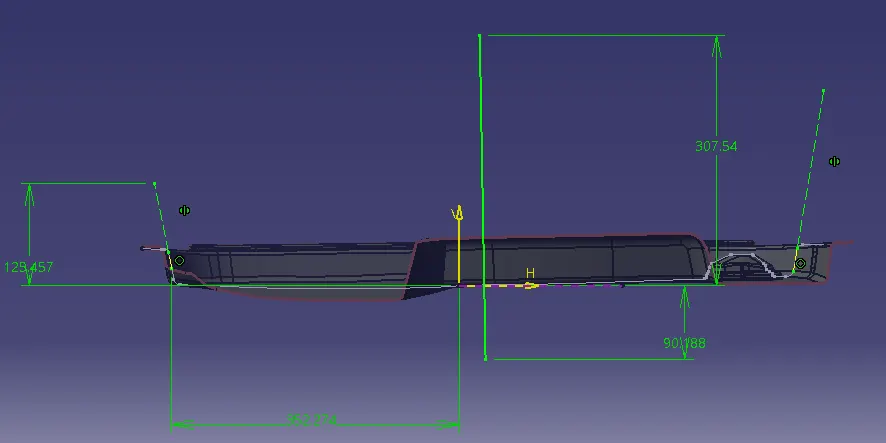
- First I extracted the suitable surface and created the "Ref. point" then created the axis system in that point and applied intersection bye XY plane. Then inserted a position sketch in same plane and created two lines bye by projecting two wall lines from the intersected curve then created one line by the bisecting method from those two lines.
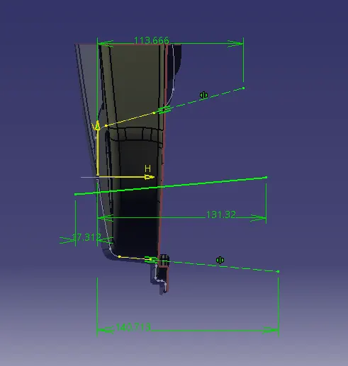
- Then intersected again at the 90 degree and again inserted another sketch along that plane in which created two lines bye by projecting two wall lines from the intersected curve then created one line by the bisecting method from those two lines.
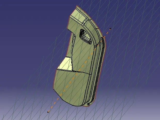
- Then bisected those two lines to get the "Tooling axis".
-
Creation of Class B & C and Solid Body
- Created the Class B surface by offsetting the whole Class A up to the thickness of the component, then created the missing surfaces by extrapolating & trimming.
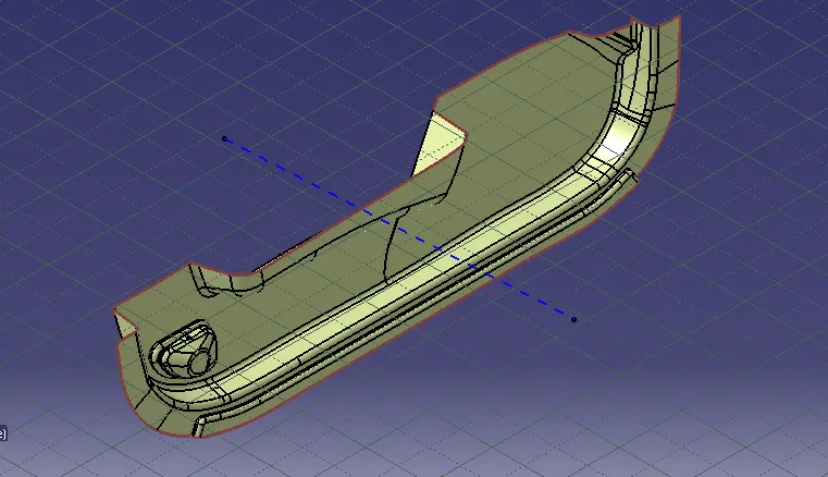
- Also created the Class C by using extrapolation and trim command.
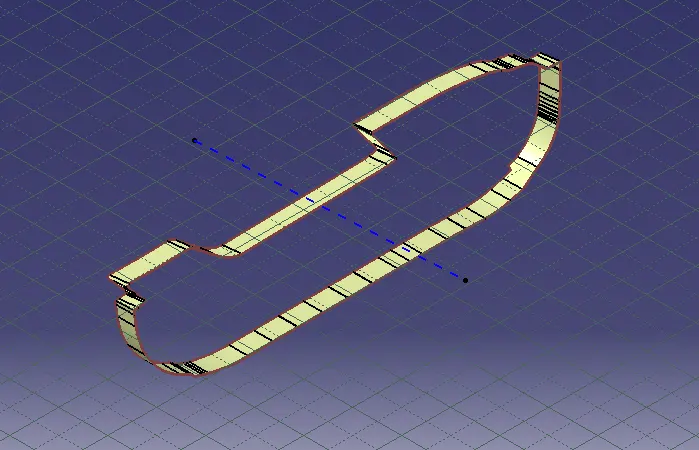
- Joined all of them, made the closed surface and applied the closed surface command to create the "Solid Body".
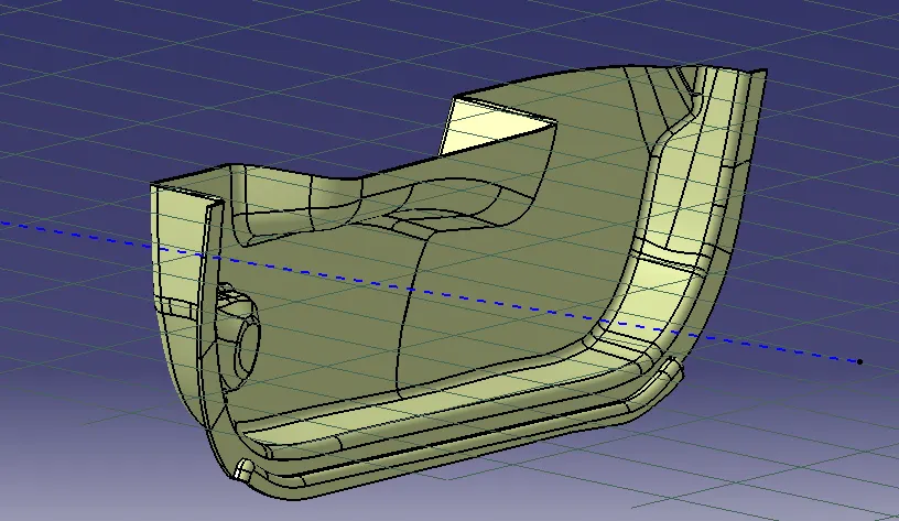
- Final Closed surface (Before Dog House)
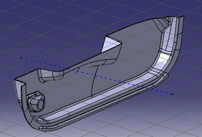
- Solid Body (Before Dog House)
-
Dog House Creation
- 1st I extracted the surface where the Dog House will be located, taken two points as per the provided drawing for Dog House.
- Then sketched on that surface at those points and sweept them till 30mm, with 1.5° draft with respect to the "Tooling Axis".
- Covered the upper side of the sweep by extruding and then trimmed it and gave fillet of 1mm to the edges. Then added a new part in part workbench and thicken the surface.
- Then extracted the outer surface of both side, back and top wall. Then gave offset of 28mm to the top extract towards down and gave offset to both the side & back extract of 1mm towards inner direction and trimmed them.
- Then I split the solid part with that recent trimmed surface to have Doghouse wall thickness of the part wall as 1mm, height of the intersection wall approx 5mm. Height varries because of draft.
- After giving the minimum fillet of 0.5mm to the remaing edges, Dog House 1 & 2 are ready whose picture is attached below.
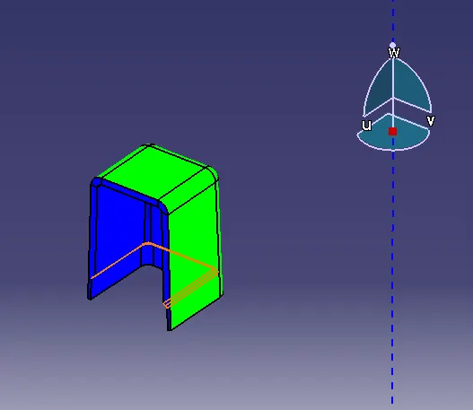
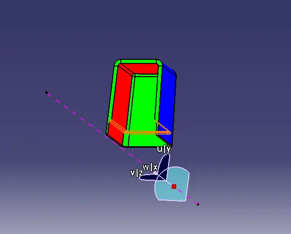
- Here Doghouse 1 & 2 both have the same dimention and creation process.
-
Draft Analysis
- For draft analysis I clicked on "customize view parameters" on view mode and selected "material", then went to Insert > Analysis > Feature draft analysis.
- The default analysis mode is "Quick analysis mode". In this mode only three options are there, just like the below image any surface of the angle above 1.4 degree will be green, any surface with the angle above 0 to 1.4 degree will be red and surface with the angle less than 0 will be blue.
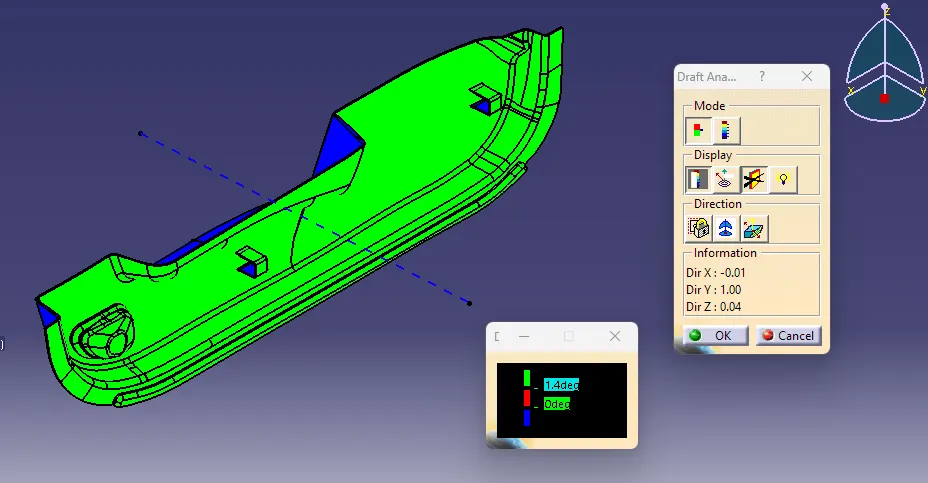
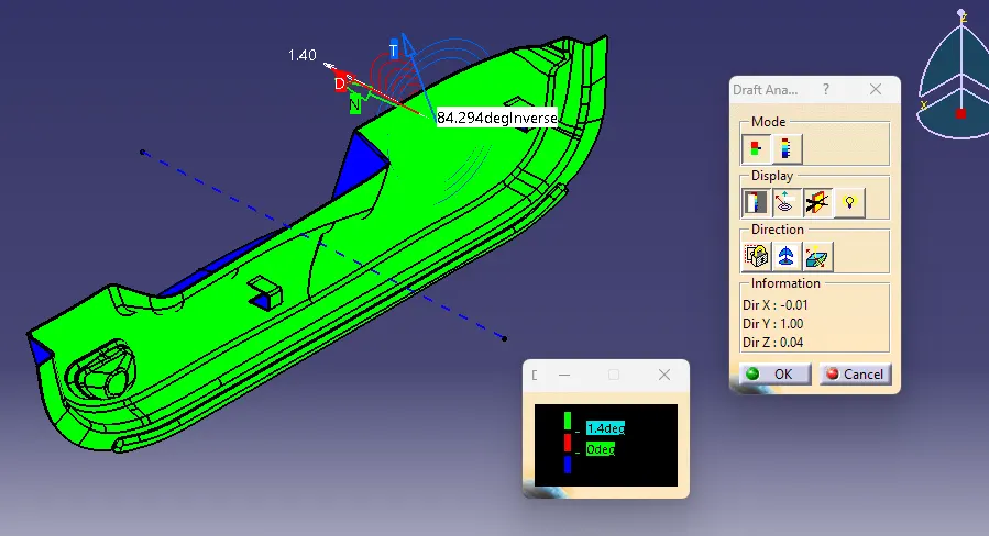
- In display section first option is color scale option, which changes the surface colors as per their draft angles. Second option is analysis under running point, in this option draft angle can be checked at any point. You can see the below image it is showing 84.294 deg. on that point after selecting that option. Rest two options are for changing the light effects on the part while draft analysis.
- In direction section first option is for locking or unlocking the draft direction. Second option is compass selection for defining draft direction, which is shown in the below picture. Third option is inverses the draft direction.
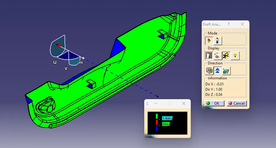
- Basically while analysing the draft angle first on the view mode I selected customized view parameters & then selected material on the next dialog box. Then brought the compass near the tooling axis and aligned with it. Checked the angles with the color scale option and also checked the angles by analysis under the running point. Checked the angles with the color scale images of the solid body in various orientations are attached below.
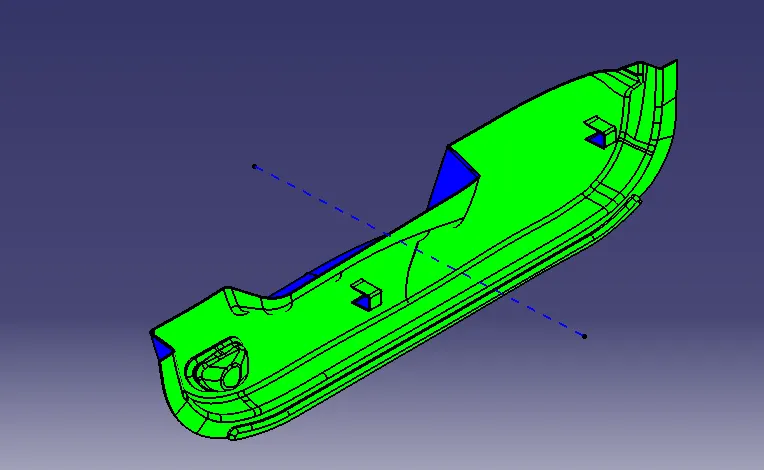
Isometric View
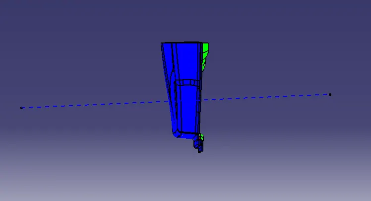
Front View
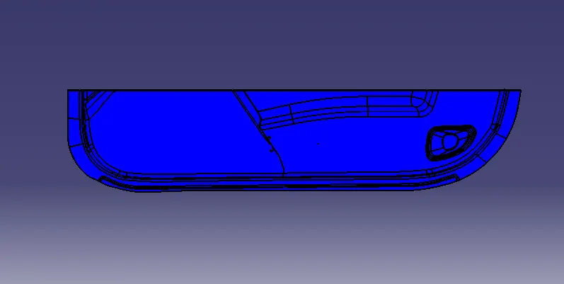
Side View
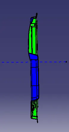
Top View
Thanks & Regards
Lohit Tripathy