Week 9 - Challenge 2 - Switch Bezel Design
OBJECTIVE
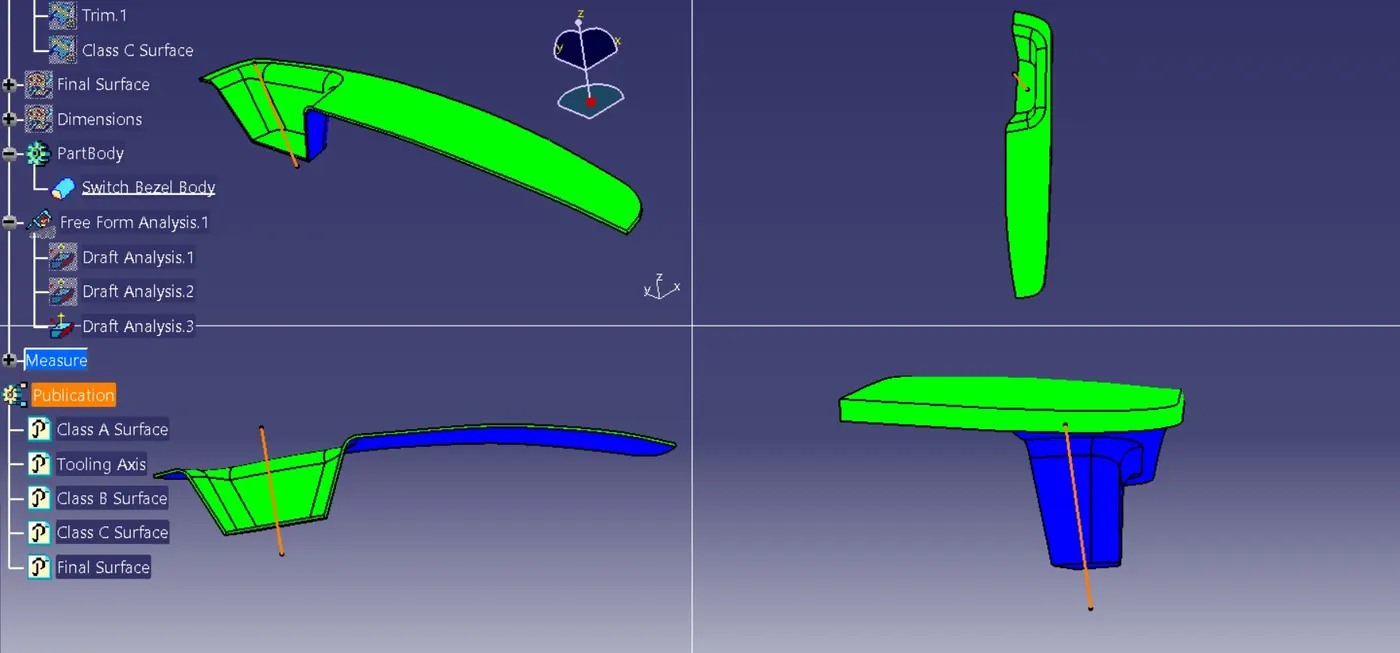
To create the Switch Bezel Plastic component from given input Class-A surface. Tooling axis for the given input Class-A Surface should be created meeting the requirements of the draft angle and at the end perform the Draft analysis for the final model.
INTRODUCTION
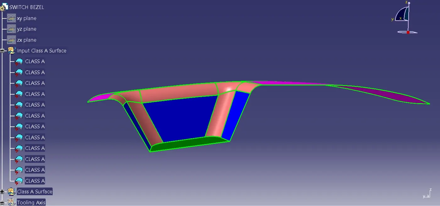
Given input Class A Surface
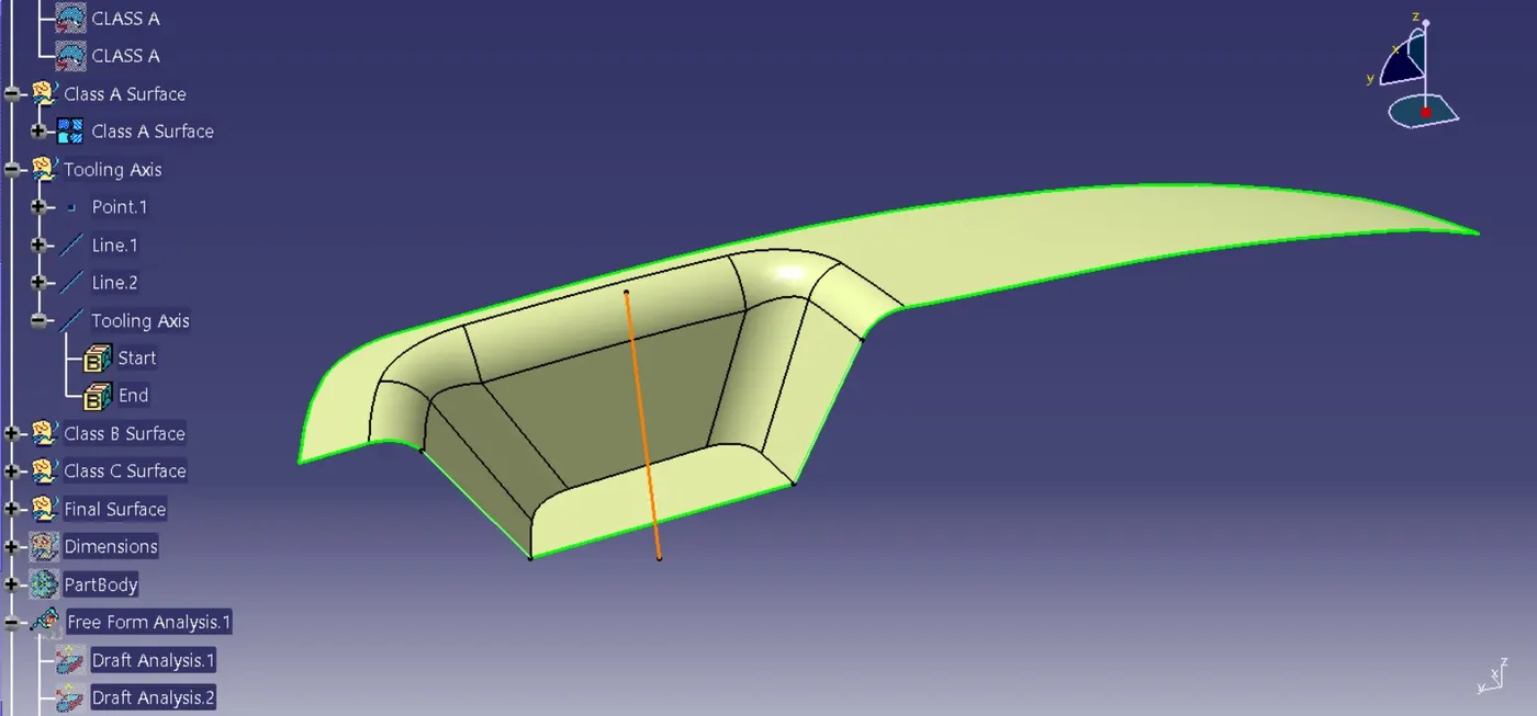
Tooling Direction or Axis
The Tooling Axis is the direction in which the mold pulls apart from the casting. As the mold is constructed in two independent sections; Core and Cavity. The Tooling Axis is formed when the Core separates from the Cavity. Also the ejection of the part from the mold is determined by the draft angle. A zero draft might cause shrinking, which could lead to difficult or no ejection. Hence for all plastic component manufacturability, the draft angle is given 3 degrees.
Steps involved in creating Tooling axis:
1. Create a point on Class A Surface. Here for the switch bezel design, create a point on the surface..
2. Create two lines using the points on curve using Point-Point command.
3. Choose bisecting command in Line to create the Tooling axis with the two line created on curve and Point 1.
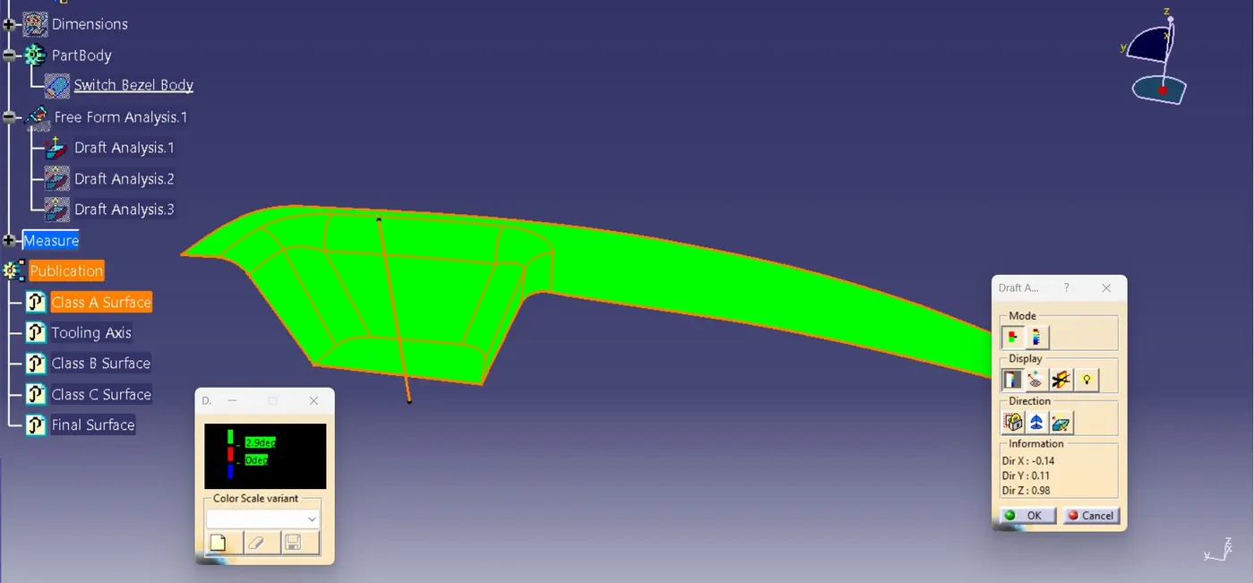
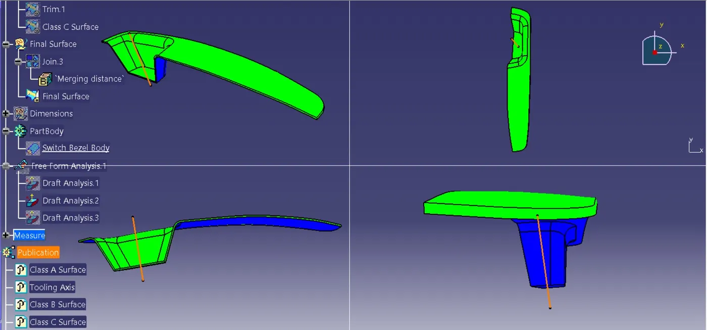
Draft Analysis
Choosing the class A surface perform Feature Draft Analysis with respect to Tooling Axis. Green colour indicates the surface can be manufactured using core and cavity method.
DESIGN METHODOLOGY
Commands used in creating the model:
- Join
- Intersect
- Point
- Line
- Extract
- Surface Untrim
- Offset
- Extrapolate
- Boundary
- Split
- Trim
- Curve Smooth
- Sweep
- Edge Fillet
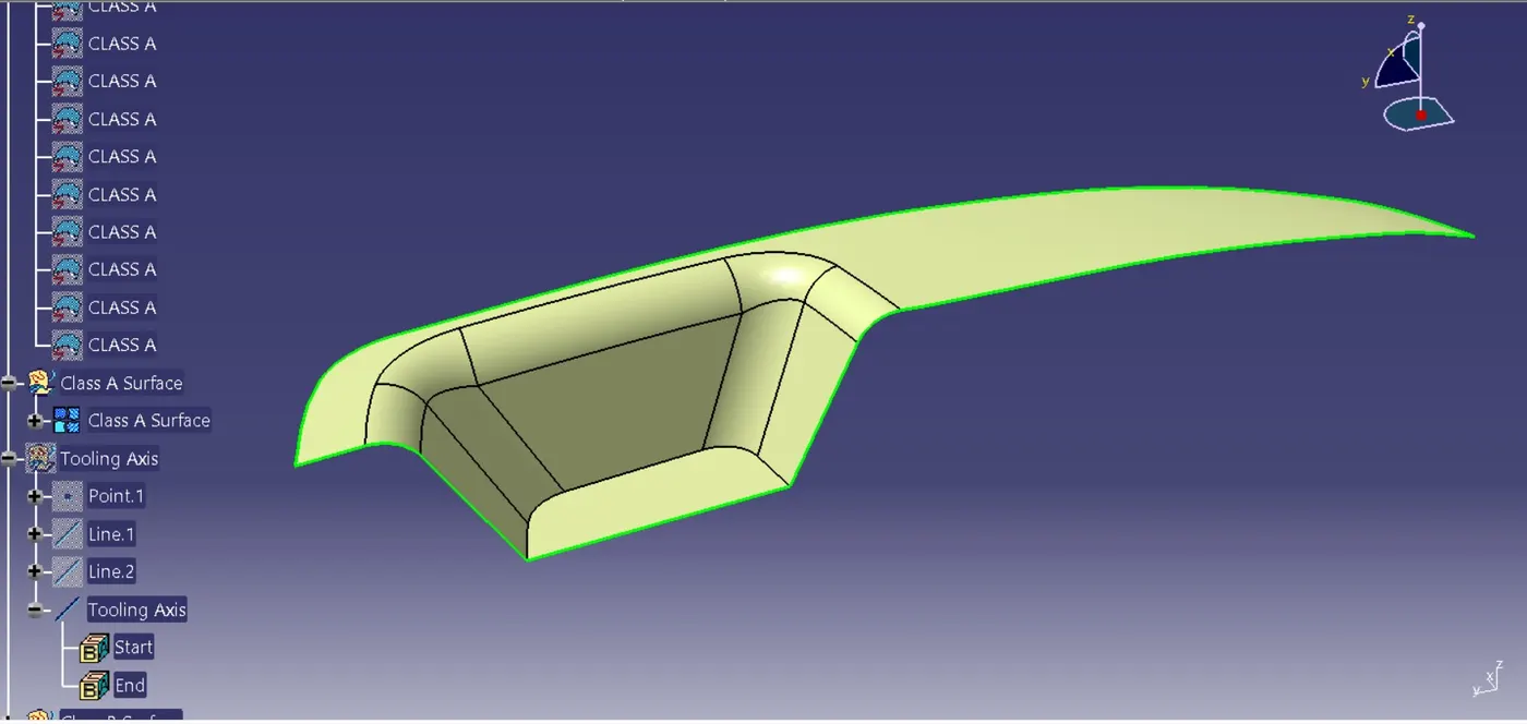
Class A Surface
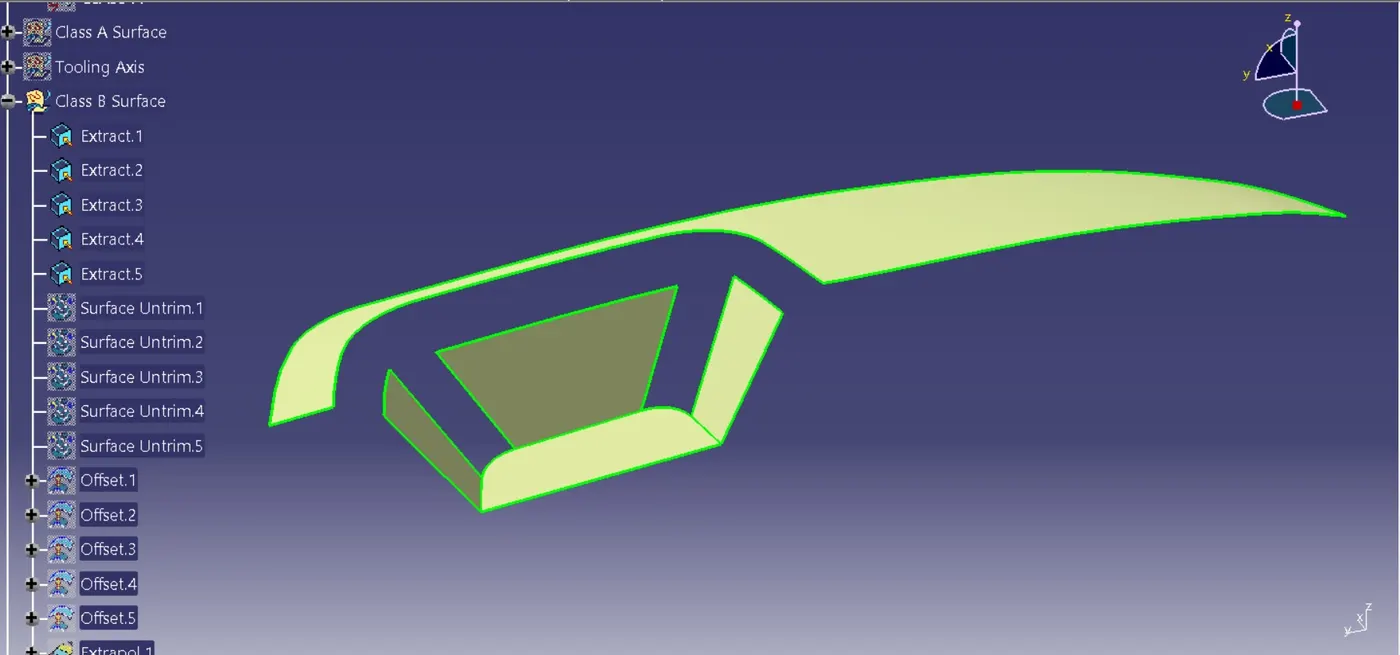
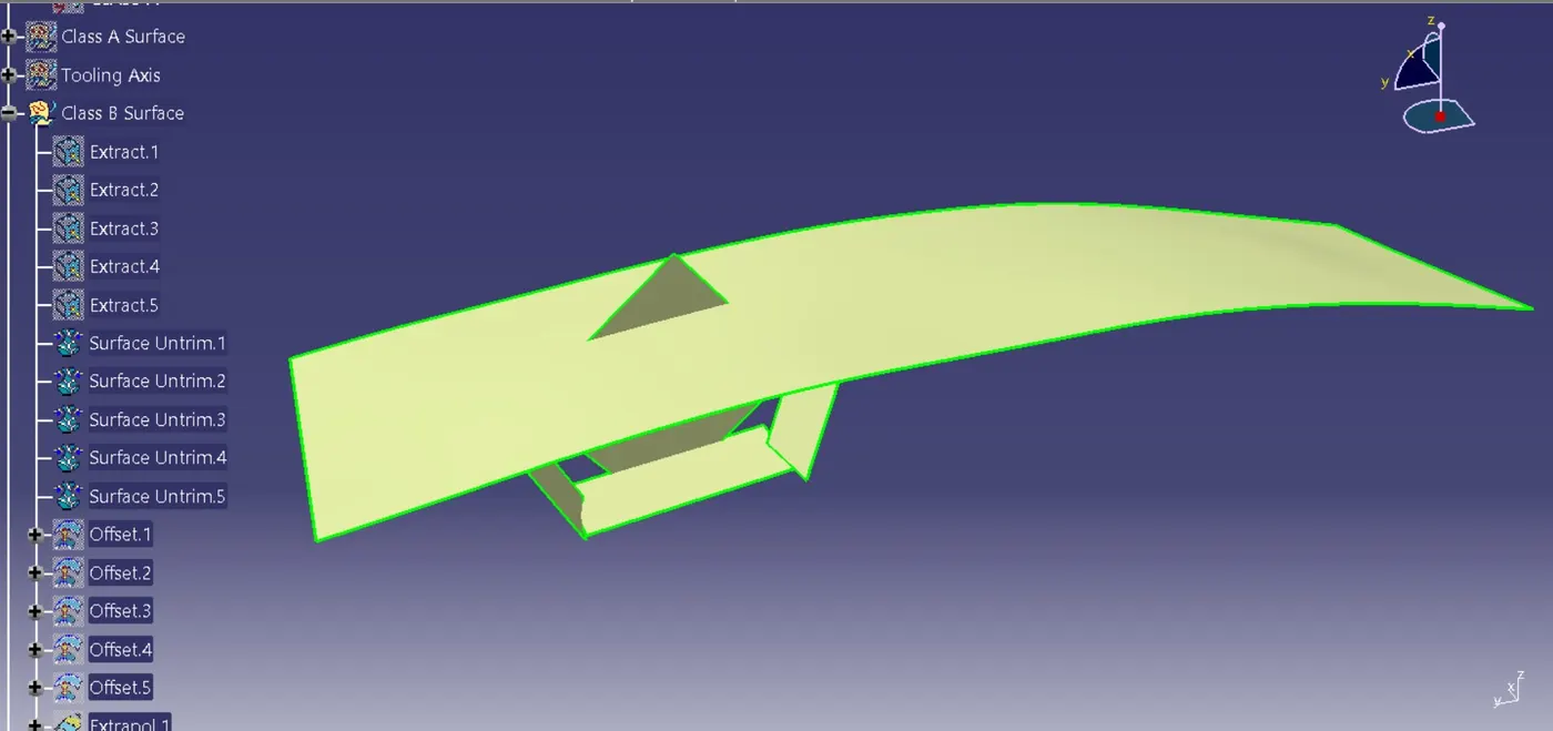
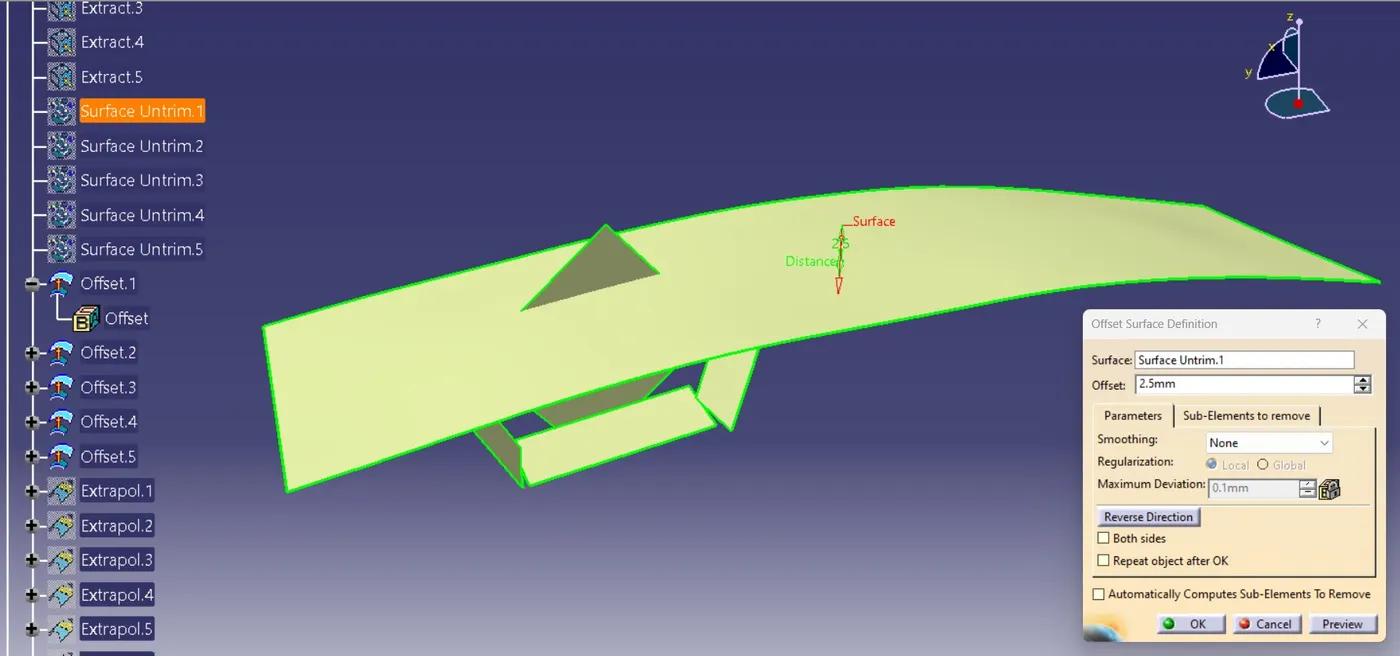
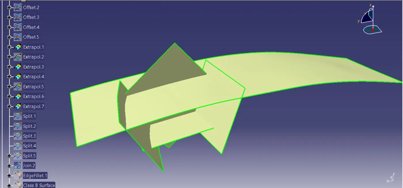
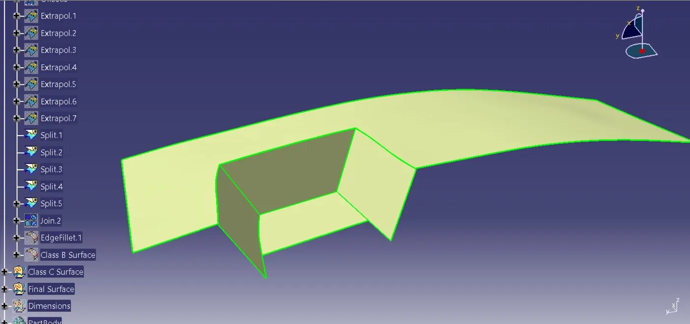
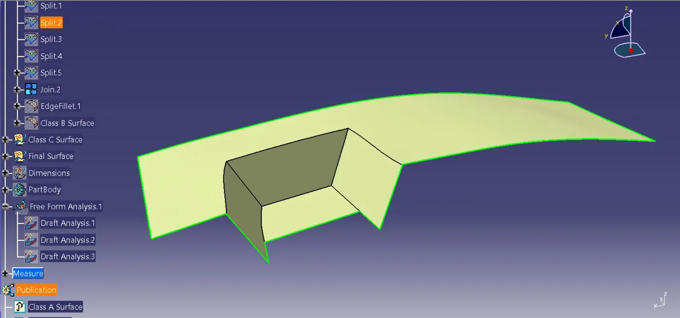
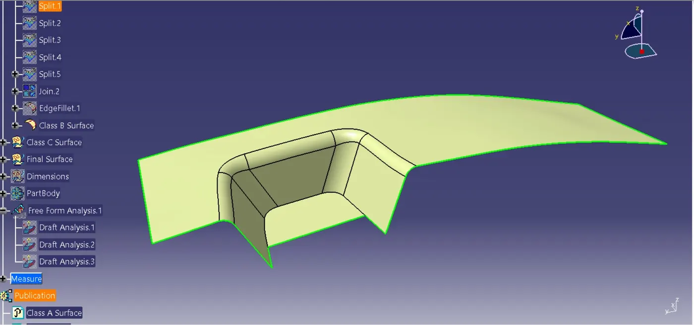
Class A surface is the aesthetic part of the model, which is already created by design engineer as input Class A Surface. Class B Surface is then created by offseting the Class A Surface according to the thickness of the part.
Class B Surface
Class B Surface is created by offseting the Class A Surface according to the thickness of the part. Here in this model 2.5mm thickness is taken.
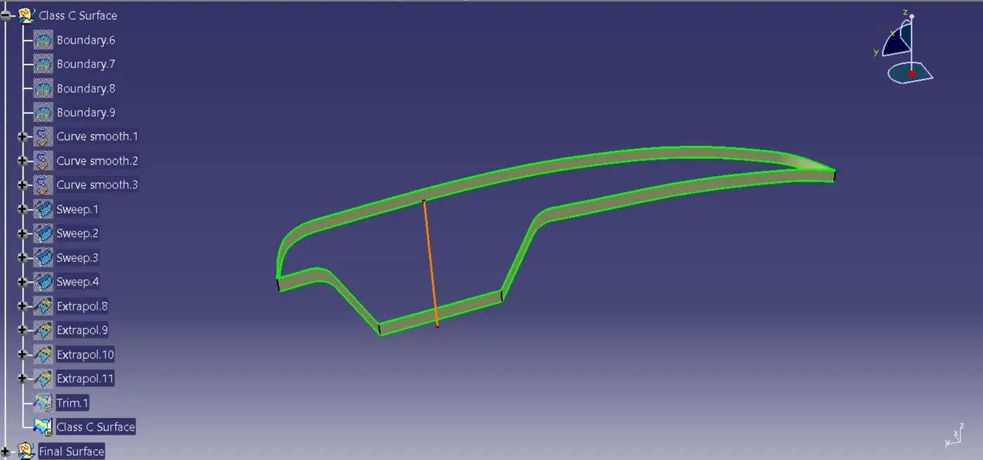
Class C Surface
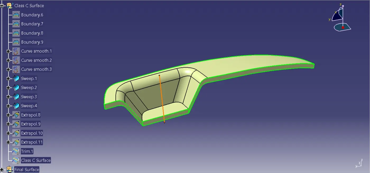
Class C Surface is the joining surface between Class A Surface and Class B Surface to obtain the plastic model.
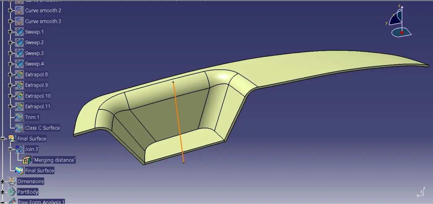
Final Surface
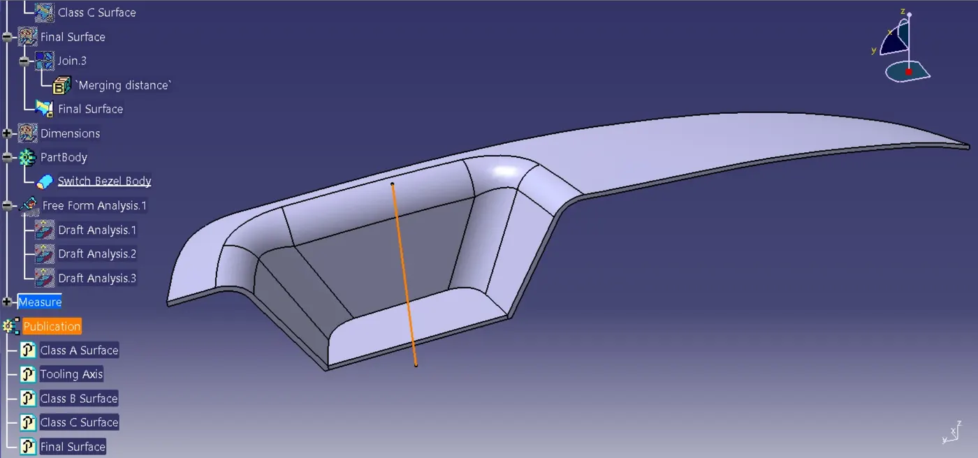
Final model is obtain by using Close Surface command from Surface based feature in part workbench.
CONCLUSION
From the given input Class A Surface, created Class A Surface, Class B Surface and Class C Surface using CATIA. Switch Bezel solid model of the part model was obtained and performed draft analysis on both Class A Surface and final Surface clearing the required draft angle. Publications for Class A Surface, Tooling Axis, Class B Surface, Class C Surface and Final surface of switch bezel was also created using Publication Tool.