Week 9-Challenge
1 )
Answer :
Objective : Providing the different types of connections for the given model .
Step by Step procedure : First import the Frame Assembly model from the given source .
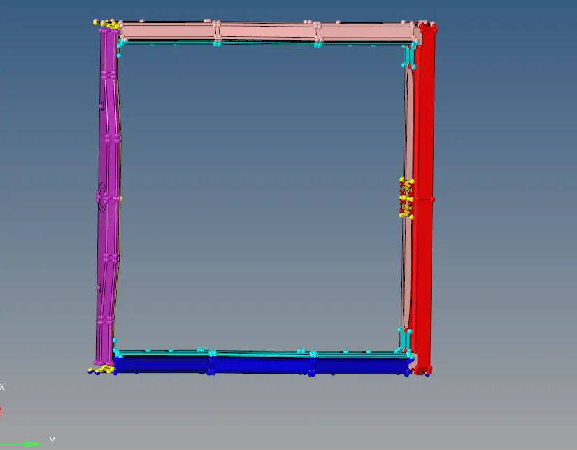
Fig 1 : Imported geometry
Mesh Generating : For the given components generate a mesh for mesh goto F12 >set the Element size 5 > select the displayed surfaces > Generate Mesh .
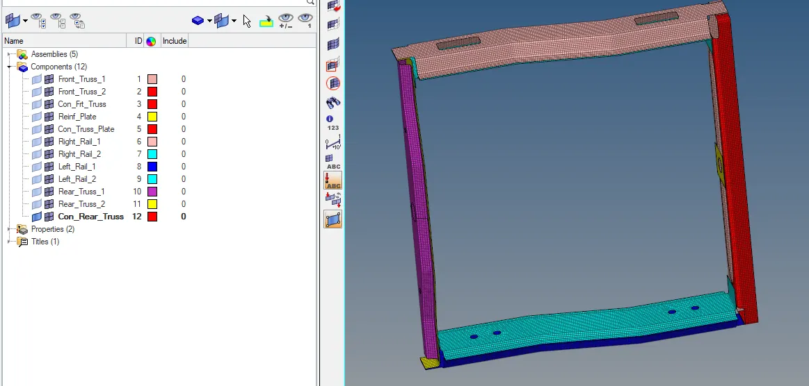
Fig 2 :Mesh Generated
Creating the connectoins : To create a connections goto 1D /2D > connectors . There are available lot of the connection options in which we can choose whiich is suitable connector for that .
Seam_ Quard (Angled +capped +L ) weld : Select the specified two components Right rai _2 & Front truss _1 For seam quard welding goto 1D/2D > Connectors > Seam > Select the which nodes to be jioninig the another component > Give the spacing as the global element size > click as Retain Nodes > selece the two components >Give the tolerence as distance depends between two component give as 10 > Goto type select as Quard (Angled+clapped +L ) >weld angle as 45 > cap angle as 60 > Run off as 10 >Create .
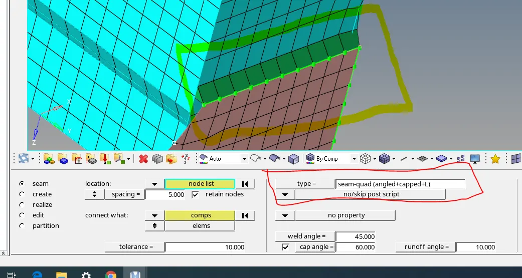
Fig 3 : Seam Quard weld
Spot weld creation : For spot weld goto 1D /2D > connectors > Spot >select the Nodes which are to be joined >select two components > select the Type as weld > Give the diameter as 5 as specified > Create.
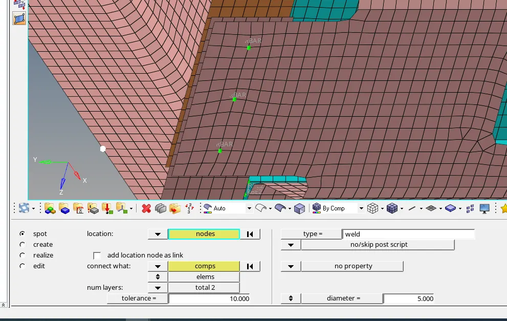
Fig 4 : weld connector
Hexa (Adhesive ) Creation : For Hexa adhessive goto 1D /2D > Connectore > Seam > Select type as Hexa Adhesive >select the nodes > give the spacing as global element size 5 > select thetwo components >give the strips, coats and width as specified > Create .
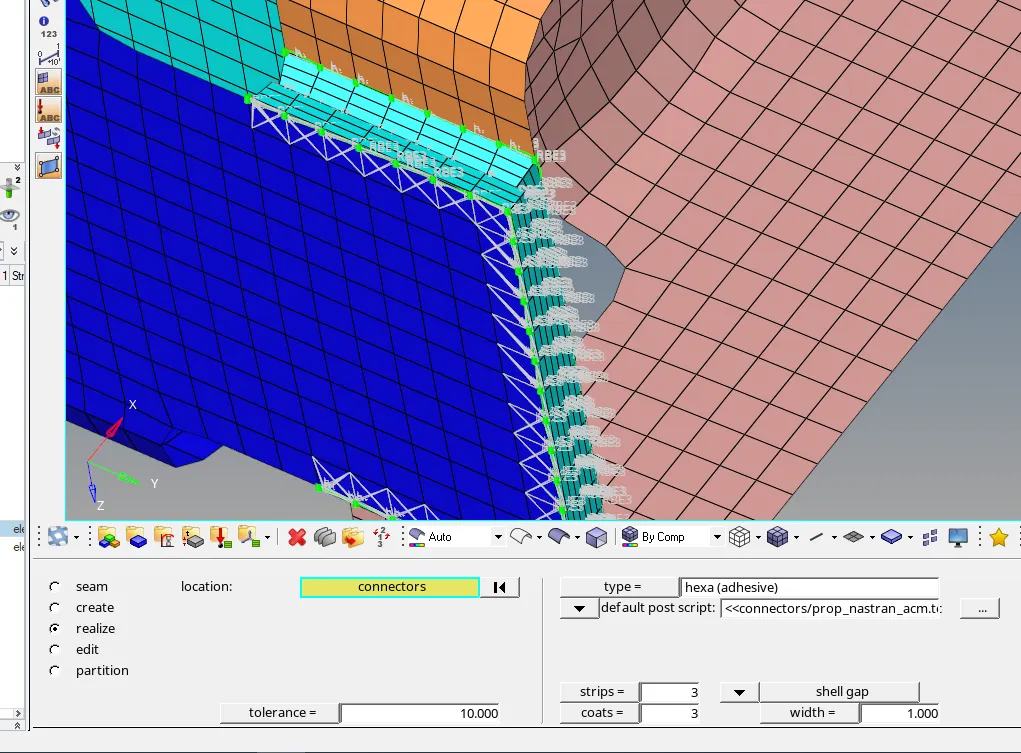
Fig 5 : Hexa Adhesive
Bolt - connector creation : For Bolt connection go to 1D/2D > Connector > Bolt > Select the Nodes > Select the two components >Give thee tolerance value >Select the Type of the Bolt > change the reate Holes if None option > Create .
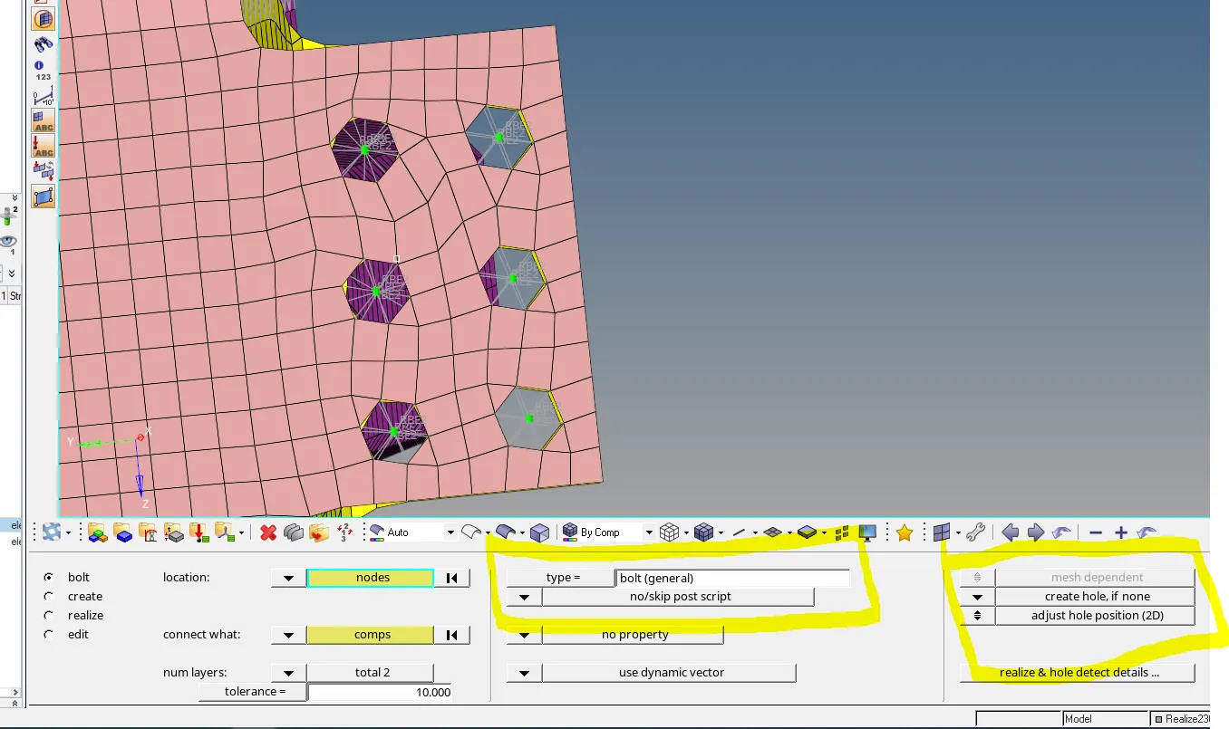
Fig 6 : Bolt creation
Like similarlly i created few connections are Hemming ,Bolt washer ,Hing ,Sealing, Cbush , C beam ,Rod connectins .
If there any connections are improper then it shows in Red colour it meansit required tochange Direction , Tolerance , Type , or some values it was done in Relize option it was done red improper connection to modify Green conection shows it means we provided connection is proper way . For Relize go to View > Browser > Hypermesh > connector > then see we maded every connections in that goto change if we required any modifications required to relize it.
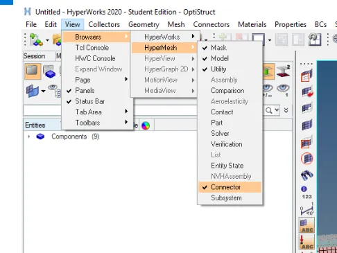
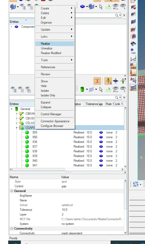
Fig 7 : Relize option
Conclusion : Due to this challenge i learned different types of connectors and how to connect components .Finally i completed this challenge with given conditions .