Week 1 Spur Gear Challenge
AIM :
In this task we will done static structural analysis on spur gear finding the total deformation ,stress and intensity of stress and compare the result values with three different materials . The total results find out in three cases those are
Case-1 :
Using Cast Iron(ductile) as a material, carry out a static structural analysis to find out Equivalent stress, Total deformation and Stress intensity(Learn about what stress intensity is). Find location for possible fracture .
Case 2:
Using Cast Steel as material, perform the same analysis for the results as in Case 1.
Case 3:
Using Cast Bronze as material, perform the same analysis for the results as in Case 1.
Introduction :
Spur gears or straight-cut gears are the simplest type of gear. They consist of a cylinder or disk with teeth projecting radially. Though the teeth are not straight-sided (but usually of special form to achieve a constant drive ratio, mainly involute but less commonly cycloidal, the edge of each tooth is straight and aligned parallel to the axis of rotation. These gears mesh together correctly only if fitted to parallel shafts.No axial thrust is created by the tooth loads. Spur gears are excellent at moderate speeds but tend to be noisy at high speeds.
Spur gear can be classified into two pressure angles, 20° being the current industry standard and 14½° being the former (often found in older equipment).[3] Spur gear teeth are manufactured by either involote profile or cycloidal profile. When two gears are in mesh at one instant there is a chance to mate involute portion with non-involute portion of mating gear. This phenomenon is known as "interference" and occurs when the number of teeth on the smaller of the two meshing gears is less than a required minimum.
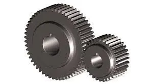
Fig 1: spur gear
Static structural :
first take static structural from design moduler then provide engineering data as per our requirement .then provide the spur gera model import it .Do the geometry cleanup if required otherwise proceed next step model .
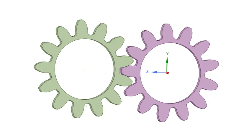
fig 2: spur gear given model
connections :
As per given gear model i provided the frictional contact for the tooth mating area and for revolute the gear provided revolute join in base of the gear .
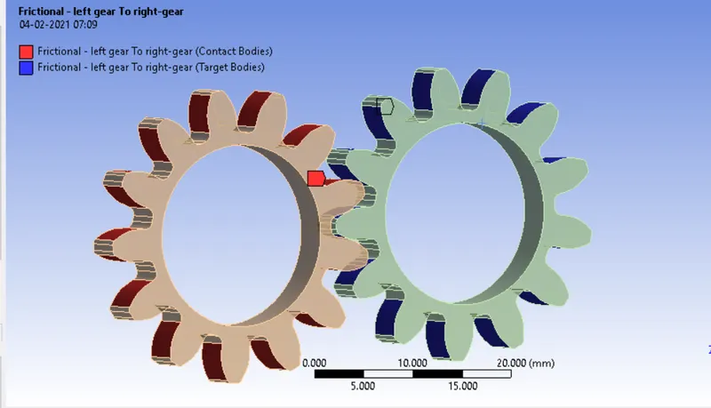
fig 3 : Contacts
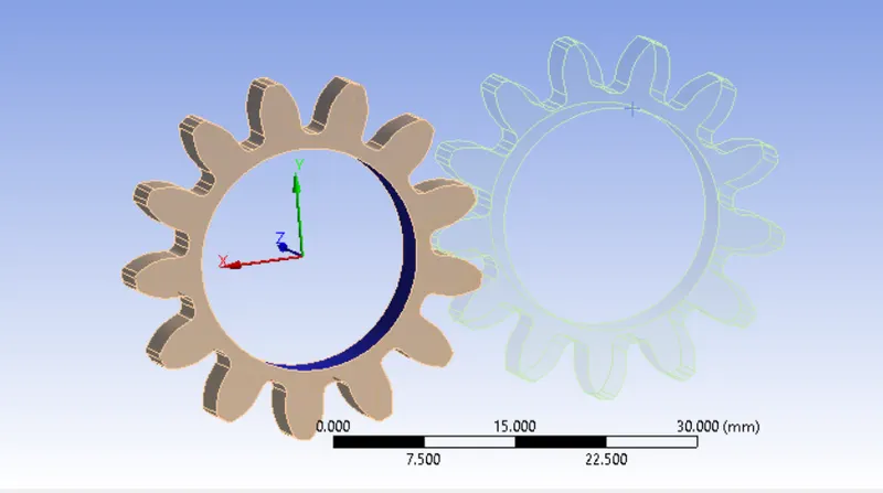
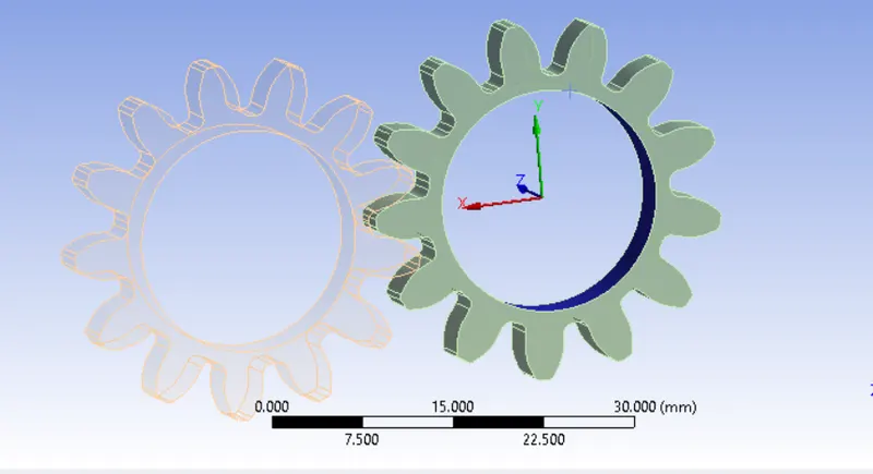
fig 4 : revolute joint for left side gear fig 5 : revolute gear for right side gear
Messhing :
for givrn model iprovided 1 mm mesh as per statistics .
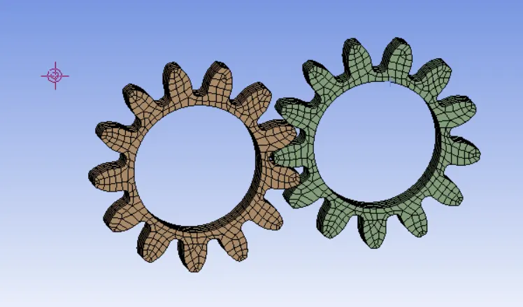
fig 6 : meshing for given model with 1mm element
Boundary conditions :
I created results in 6 steps by using analysis settings .and given the joint loads as per above provided joint connection .
here i given for for gear is rotation in angle of 30 degree of rotation in 6 steps then it will total 180 degree rotation then after another gear provided the moment load of 10 N-M in Negative value depends of first gear rotation moment will provided.
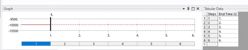
Fig 7 : total no.of steps
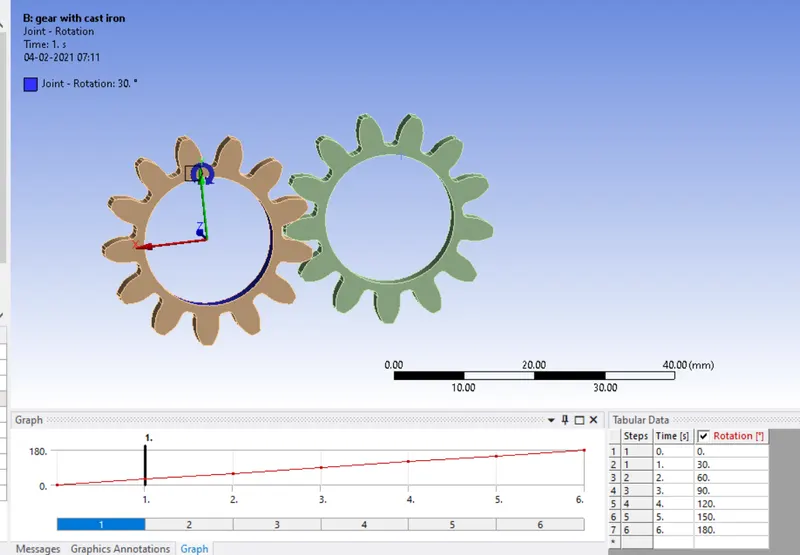
Fig 8 : rotational provided
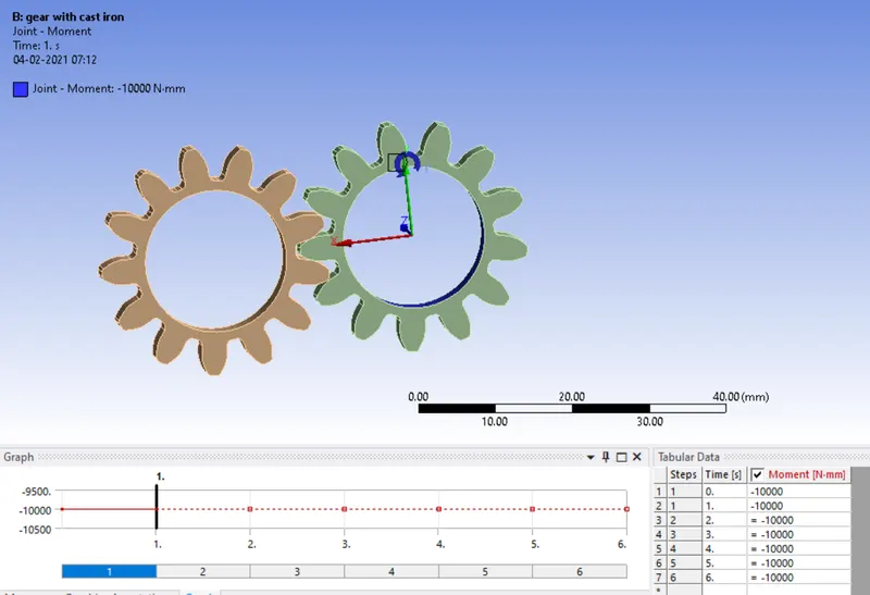
Fig 9 : moment load provided
Solution :
then after all boundary conditions and loads are provided then proceed for solution of total deformation ,equivalent stress and stress intensity of maximum values and minimum values.similarlly do for the other materials also apply material and giiven same type of boundary contacts.
FOR CAST IRON :
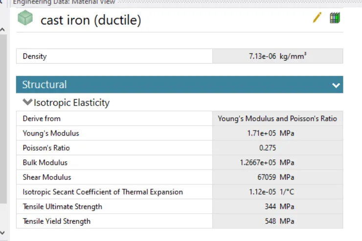
for cast iron applied material data is
Total deformation :
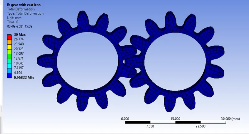
fig 10 : total deformation of cast iron
.
fig 11 : graph and tabular data of cast iron .
Equivalent stress :
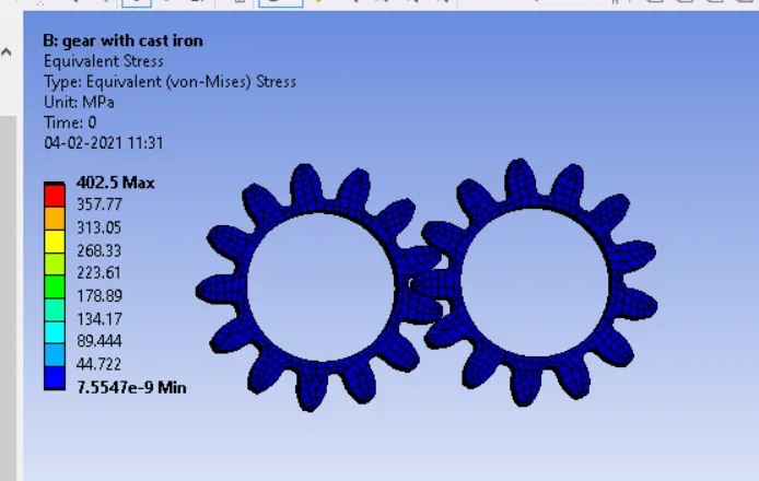
fig 12 : Equivalent stress of cast iron

fig 13 : tabulardata and graph of cast iron .
Stress intensity :
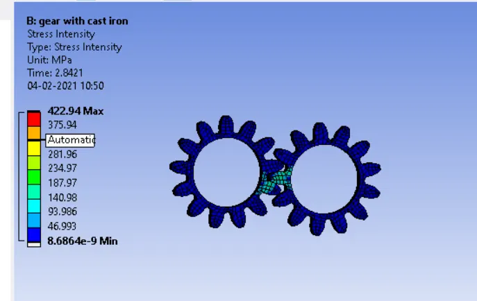
fig 14 : stress intensity for cast iron

fig 15 : stress intensity graph for cast iron
like this for other materials also
cast steel :
applied material cast steel properties are created from the engineering date
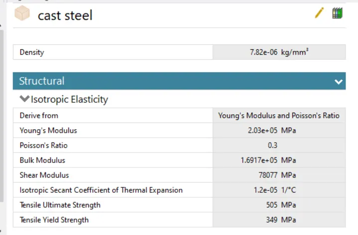
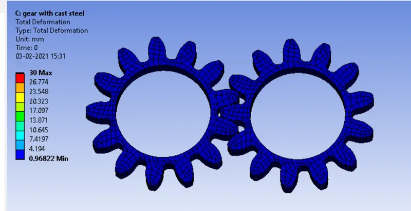
fig 16: total deformation of cast steel
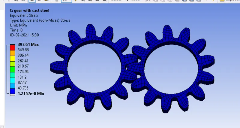
fig 17 : Equivalent stress of cast steel
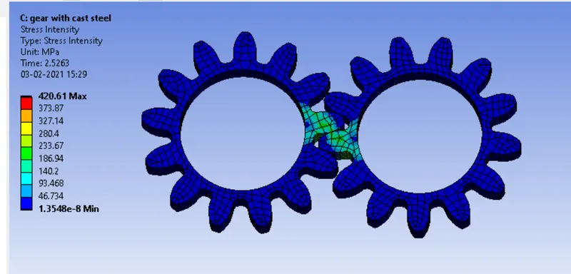
fig 18 : stress intensity of cast steel
Bronze cast :
for bronze cast material properties are
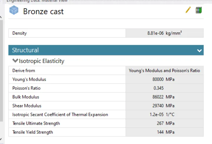
fig 19 : material properties of bronze cast material
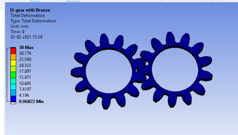
fig 20 : total deformation of bronze cast
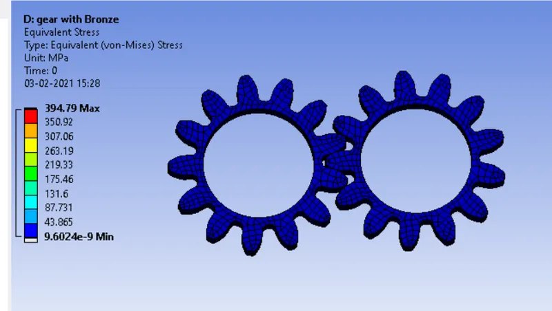
fig21 : Equivalent stress of Bronze
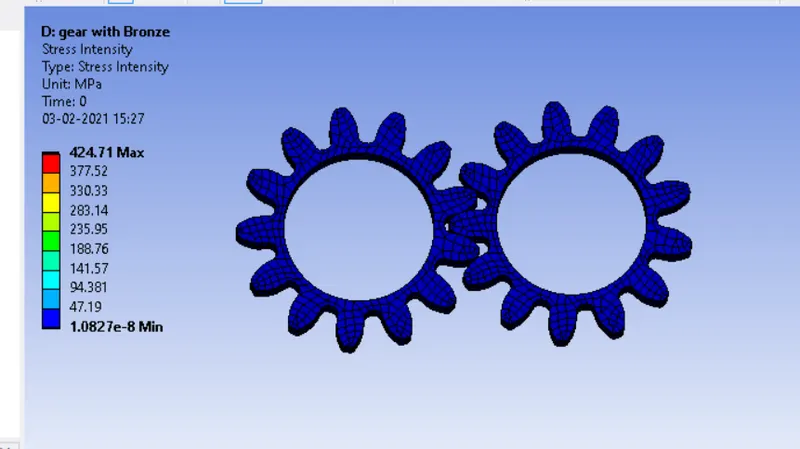
fig 22 : stress intensity of bronze
from the above three materials applied for spur gear then after solution came we compare the three among three materials
| material |
max. deformation( mm) |
min .deformation (mm) | max . equivalent stress (mpa) | min . equivalent stress (mpa) | Max stress intensity(mpa) | min . stress intensity(mpa) |
| cast iron | 30 | 0.96822 | 402.5 | 7.5547e-9 | 422.94 | 8.6864e-9 |
| cast steel | 30 | 0.96822 | 393.61 | 1.2157e-8 | 420.61 | 1.3548e-8 |
| bronze cast | 30 | 0.96822 | 394.79 | 9.6024e-9 | 424.71 | 1.0827e-8 |
Fig 23 : Tabular data for compaing all maximum and minimum values for the all solution parameteres for three maerials
conclusion :
After comparing all three materials evary material got failured when compared to there youngs modulus values every material getting theire maximum values with comparitevely . cast iron getting high equivalent stress and stress intensity also .among all three materials BRONZE gives good capability when comapare to other two materials it has high youngs modulus value and it contain high ductility.