Week 4- Challenge
Answer :
OBJECTIVE : Genarating themid surface with suitable options and creating the 1D elements with applying given different cross sections and degree of freedom to the given component.
Step By Step Procedure :
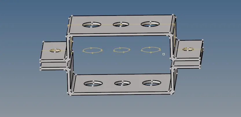
Fig 1: Imported geometry view
- First we should import the geometry from the given source.
- Then deleted the unnecessary lines from using F2 >put LINES > Right click on lines select DISPLAY option > Delet.
CREATING MIDSURFACE
- After deleting lines for creating the MIDSURFACE for two brackets individually created two components those BRACKET 1,BRACKET 2.
- Then goto GEOMETRY >MIDSURFACE > EXTRACTION OPTION > chose OFFSET >Auto extraction >select the Bracket 1 and exract the mid surface and same step will proced for Bracket 2 also.
ORGANIZE SURFACE :
- For oranizing surface goto TOOLS >ORGANIZE >set the SURFACE insted of elements and select the BRACKET1 surface >make the destination BRACKET 1 >click MOVE.
- Similarlly do for second bracket also make destination as bracket2 select the bracket 2 surface for move.
- After completed organize goto F2 >delete SOLID select entire solid >Delete it.
- Then goto component delete remaining components except organizing components now we can see thebrackets are changed to allocated colours in components.
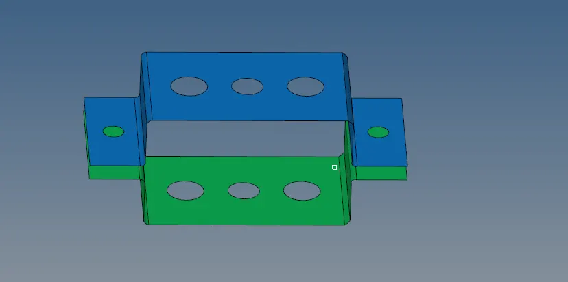
Fig 2 : Mid surface generation
QUICK EDIT :
- After completed midsurface generation we can do Geometry cleanup by goto GEOMETRY >QUICK EDIT >makr the washer split 5 mm.
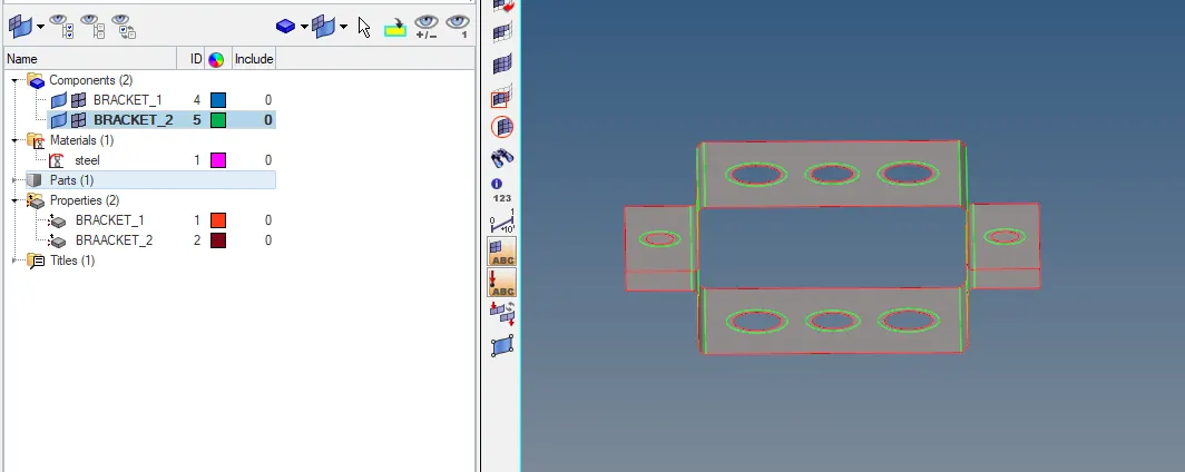
Fig 3 : Washer split
MESHING :
- For meshing goto 2D > Auto mesh > set the element size as 6mm >select the two bracket surfaces by using right click on surfaces select the DISPLAYED > make MIXED elements > mesh ..make same number of elements in outside and inside of washer .
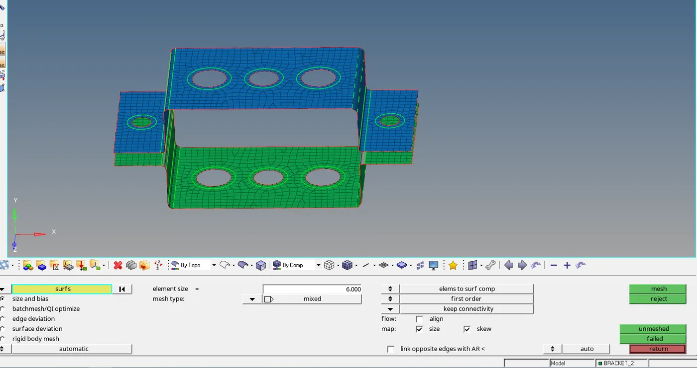
Fig 4 :Meshing of component
CREATING RIGIDS :
- For creating rigids as per given that goto 1D >for RBE 2 click RIGIDS > select the upto washer nodes of Bracket 1 then make the Degree Of Freedom as per given . we can observe the RBE 2 node is created with surrounding nodes connected.
- Like that create for rigid RBE3 similarlly above RBE2 make dof's as per mention.create the remaining rigids for hole also like that only.
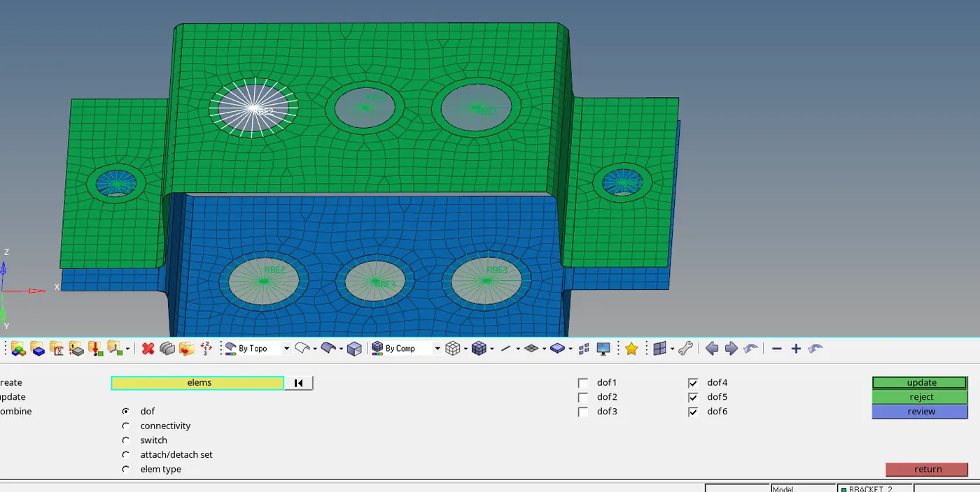
Fig 5 : Traslational DOF's for RBE2
CREATING CROSS SECTIONS :
- For creating cross sections we can move to 1D > HYPERBEAM > STANDARD SELECTION >for type of cross section we can chose as per required dimensions for differt cross sections for first one click on thin walled box> click CREATE give dimensions as our requirement .
- Like that create the different cross sections are I section and the STANDARED CHANNEL also..Then rename the cross section names as per 1D element for easy understand to connecting the 1D elements for our convinient.
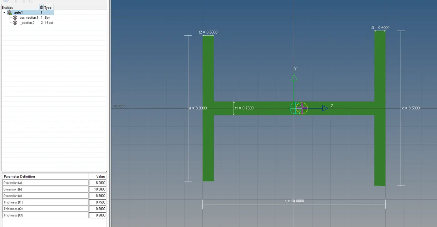
Fig 6 : Creating of I-cross section as per given Dimensions
MAKING OF 1-D ELEMENTS :
- After completed the creation of cross sections create the 1D elements for connecting the rigids and apply the cross sections to them.
- First create the property of which 1D elements we are creating . create ROD, BEAM, BAR as we required .click on property of rod >ste CARD IMAGE as PROD > beam section as ROD.
- like that apply the property of Beam card image as PBEAM for BAR apply PBAR.
- For creating 1D elements goto 1D > ROD >CREATE >select the spicifies nodes from bracket 1 and bracket 2.>set the property as ROD and element type CROD> UPDATE >select the created 1d CROD rod element >click update.
- Similarlly do for BAR >select nodes from given places >property select the BAR > Element type CBAR >UPDATE the element.do for beam also same.
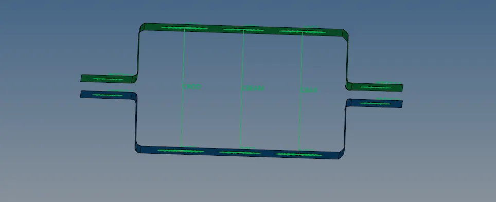
Fig 7: 1D view of ROD,BEAM ,BAR
- For creating springs > 1D >springs >select the corner nodes .
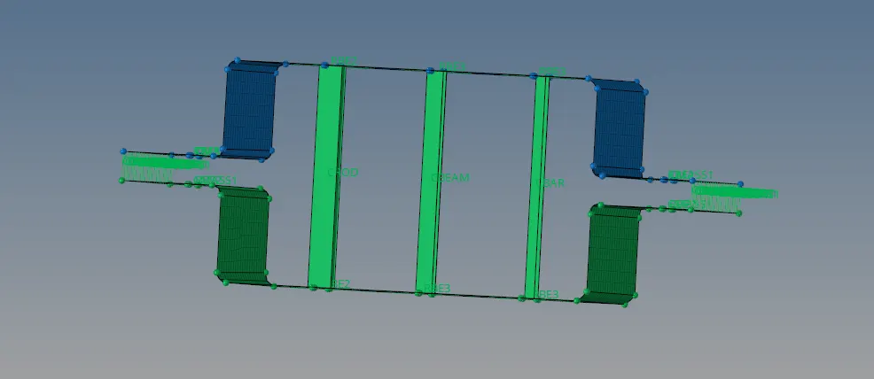
Fig 8: Spring view at corners
- Finally forseeing the sections view make the 1D traditional view to 1D detailed view
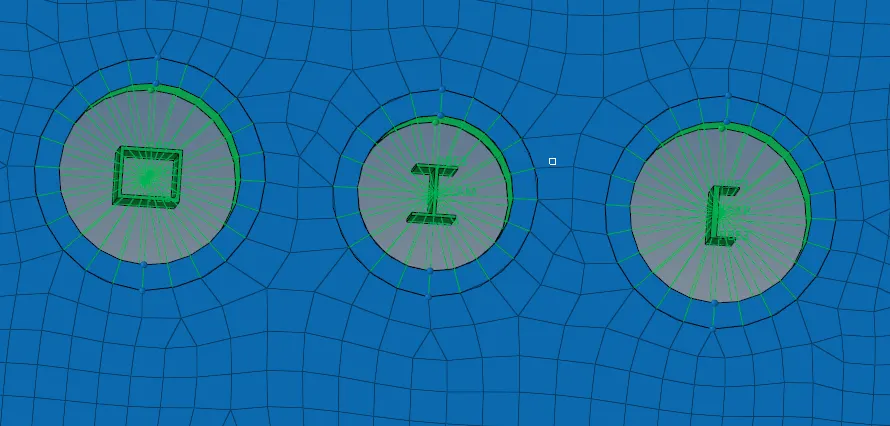
Fig 9 :Top view of cross sections
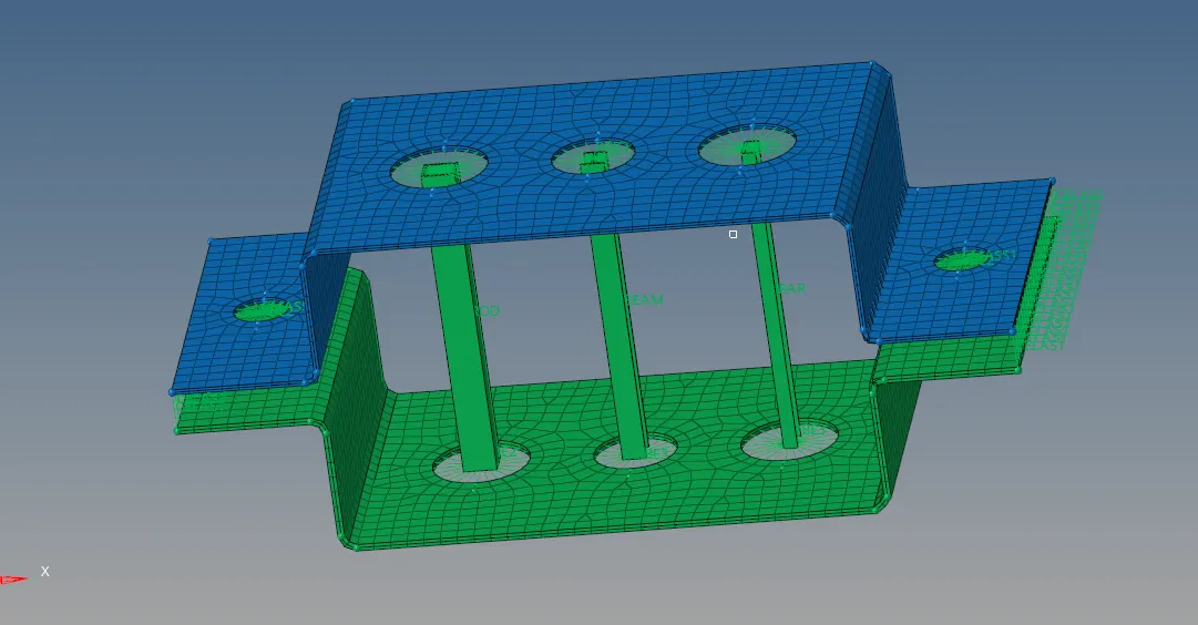
Fig 10: Front view of updated cross sections
conclusion :
Finally task is completed with give requirements .In this very well know about making 1d elements as detailed.