Week 9 - Challenge 1 - Base Bracket Design
ANSWER
AIM
The creation of a Base Bracket Plastic Component using a specific Class A Surface, followed by the completion of a Draft Analysis on the plastic component.
OBJECTIVES
- Creation of Tooling Axis.
- Creation of Class B and Class C surface.
- Creating a solid part out of surface modelling.
- Draft Analysis of Class A surface and final plastic component.
INTRODUCTION
In this project, we're using a class A surface to create a base bracket. The method calls for the construction of a Class B surface with the entire component's 3 mm thickness in mind. In the plan, Class C creation from the provided progenitor surface was also included.
CLASS A
To proceed with the design process, we must first determine the tooling axis for the surface and use CATIA's Draft Analysis tool to check for all draughts.
DRAFTING SURFACE FOR SURFACE A
An study of a 3-degree draught is conducted. As is evident, every surface is warmer than 3 degrees.
TOOLING AXIS CREATION
- Make a CLASS junction Create the cutting axis as shown by intersecting a surface with the ZX plane.
- Use the lines in the image to create a bisecting line.
CREATION OF CLASS B
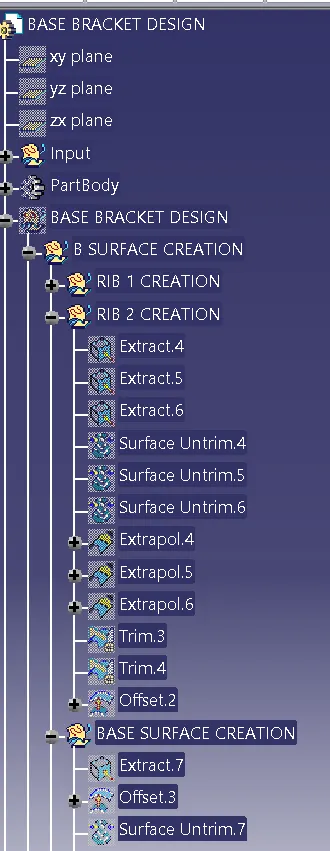
- In order to create Class B, we first extracted the progenitor surface from Class A and then untrimmed it.
- The necessary thickness is then offset onto these surfaces.
- Following offset, each surface is cut to the desired form.
- The areas receive the necessary fillets.
CREATION OF CLASS C
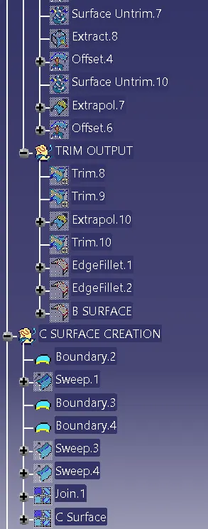
- We used multi-extract to extract the Class A boundary for this surface, which we then transformed to a smooth curve.
- This smooth curve is now swept with a 3 degree draught along the draught path.
FINAL TRIMS
CLASS A+CLASS C
We made the single body using the join option to ensure that there is no open boundary between classes A and C. To ensure that the parting line doesn't fall between these two areas, this is done.
CLASS A+ CLASS B +CLASS C
For this we have trimmed the above shown surface with the Class B surface using trim feature.
DRAFT ANALYSIS OF FINAL COMPONENT
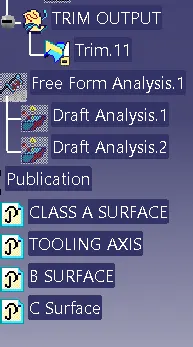
The primary tooling axis is used as a draught reference for this study.
The following outcomes were attained:
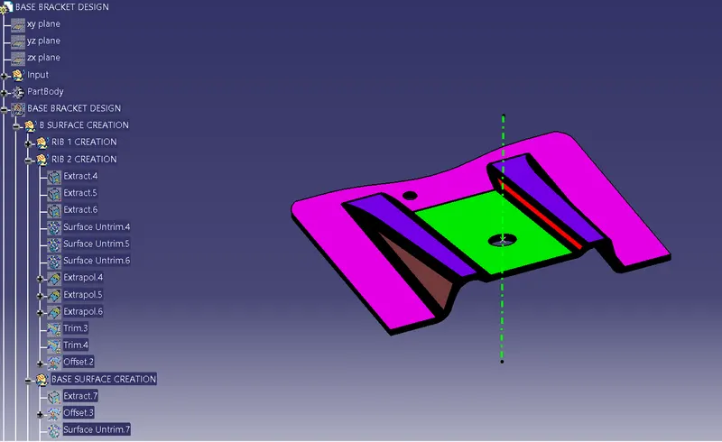
TREE STRUCTURE