Project - Speed Control of a Direct Current (DC) motor
ANSWER 1
AIM
To design a Simulink model for the DC motor shown in the question. We will also use by the Proportional, Integral, and Derivative (PID) control design knowledge gained in the course of the pogram to design, develop and test a controller to maintain a desired speed for the motor.
INTRODUCTION
- In this the speed of these DC motor is given manually or by a automatic control device.
- It is different from the case where the speed is regulated or trying to be maintained against natural speed due to change in load of the shaft.
- speed is carried by changing
- The Flux of the pole
- The terminal voltage of the armature V
- The External resistance of the armature circuit Ra
- Both the terminal voltage and external resistance involves a change that affects the armature circuit while flux involves a change in magnetic field.
- The 2 methods to control speed of Dc motor are armature control methods and field control methods.
ARMATURE CONTROL METHODS
In an armature control method when we add resistance in series with the current decreases.It results in change of speed of the motor and back EMF.
FIELD CONTROL METHODS
It can operate under normal speed and result in less torque.The field control methods allows to obtain higher speed than the norms.The overall can be lowered due to stability.
MATLAB CODE
SIMULINK MODEL
- We will first create a simulink model for a DC motor and make it a subsystem called DC motor.
- The subsystem will be connected to discrete PID controller for maintaining the speed.
- The initial values of Kp,Ki &Kd are taken as 1.0, 1.0&0 respectively.
- To obtain the objectives the values of Kp,Ki &Kd are taken as 31.5,82.3& 2.3.
SIMULINK MODEL OF A DC MOTOR
CASE1 SUPPLY VOLTAGE 230V
CASE2 SUPPLY VOLTAGE 100V
CASE3 SUPPLY VOLTAGE 75V
CASE4 SUPPLY VOLTAGE 50V
CASE5 SUPPLY VOLTAGE 25V
CASE6 SUPPLY VOLTAGE 10V
SIMULINK MODEL FOR A DC MOTOR WITH PID CONTROLLER
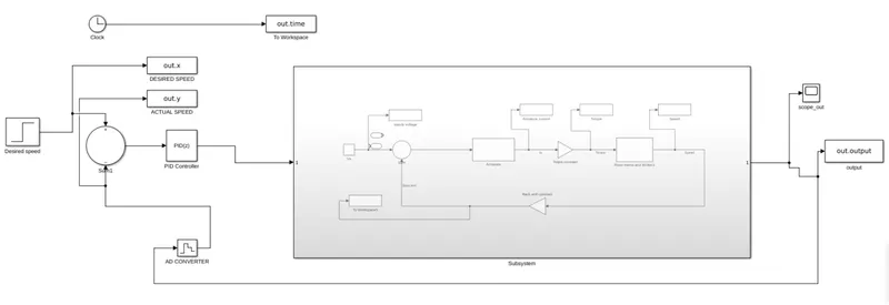
CASE1 Kp=1.0,Ki=1.0&Kd=0
CASE2 Kp=31.5,Ki=82.3&Kd=2.3
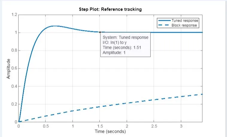
PLOT WHEN TURNING TIMEIS 1.5 SEC
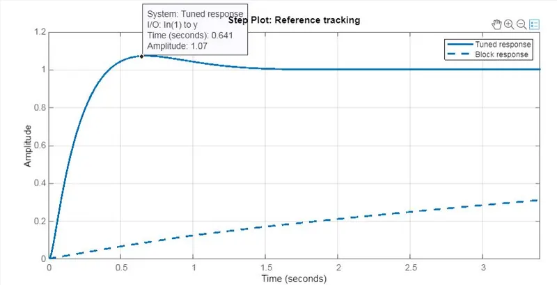
PLOT WHEN OVERSHOOT IS LESS THAN 5%
PLOT WHEN STEADY STATE ERROR IS LESS THAN 1%

FINAL PLOT
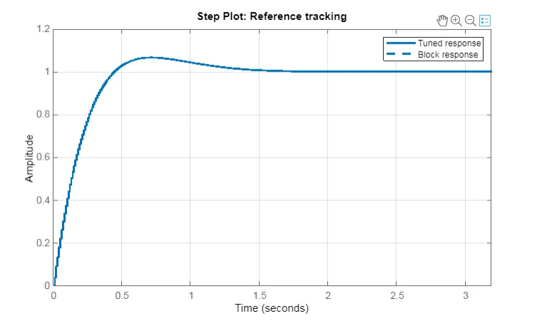
FOR MAINTAINING THE STABILITY
OUTPUT RESULTS
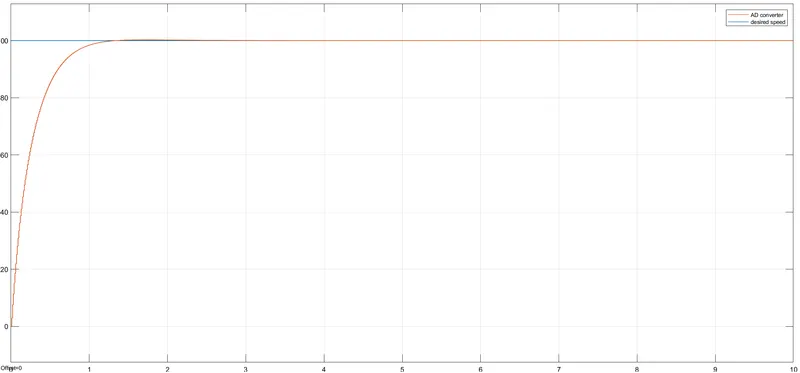
Case1 When the speed of motor is 100
Case2 When the speed of motor is 230
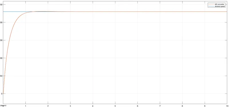
The values are given inorder to attain the objectives which include setting time.overshoot time and steady state error.
We have considered two cases in which the speed of motor is taken as 100 and 230 respectively.But from the plot it is clear that they are almost the same.So we can conclude that we maintained the speed of the motor.
CONCLUSION
In our project we have developed a simulink model for a DC motor as shown in the figure.Supply voltage is changed to analyse the variation of output plots. Supply voltage, Back emf , Armature current, Motor torque, speed are plotted under different supply voltages(10,25,50,100 & 230). The overshoot value and steady state errors are increased with increase in supply voltage. Better response is obtained at lower supply voltage cases. Below 2 second setting time is obtained at lower supply voltage.Below 5% of overshoot is obtained at lower supply voltage. Below 1% of steady state error is obtained at lower supply voltage. In the second case we have developed a PID controller to the model of the DC motor with Kp=31.5,Ki=82.3& Kd=2.3. We have considered two cases in which the speed of motor is taken as 100 and 230 respectively.But from the plot it is clear that they are almost the same.The PID was designed based on the knowledge obtained in the training session.Using this we will be able to control the speed of the motor.