Week 9 - Challenge 1 - Base Bracket Design
BASE BRACKET DESIGN
AIM: Design base bracket component from the given class-A surface.
METHODOLOGY:
STEP I: TOOLING AXIS
In this step we are creating a tooling axis from the given class-A surface using the intersect method. In this method we created two lines, with the help of these two lines we created a bi-secting line and the tooling axis.
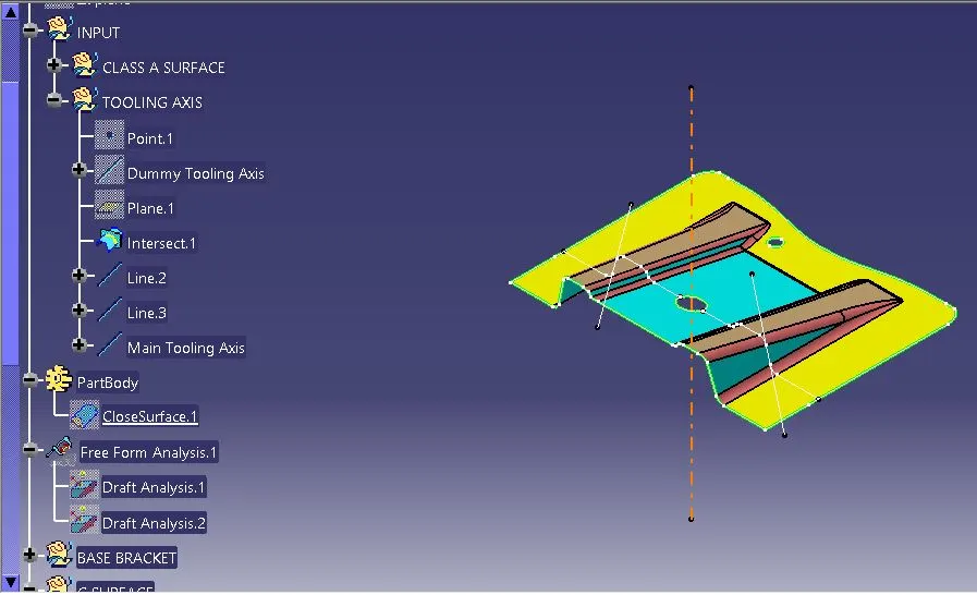
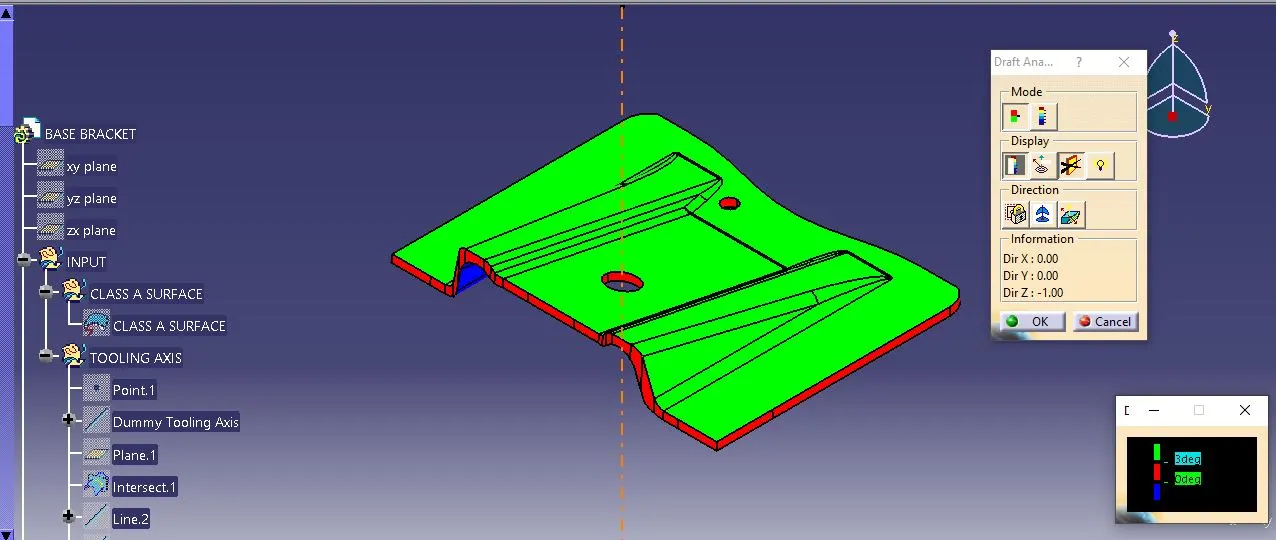
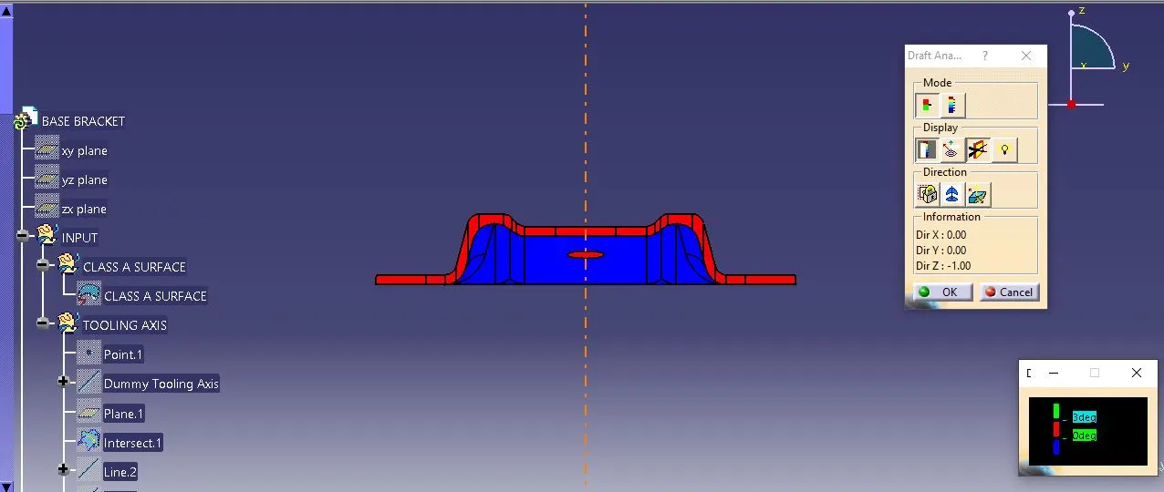
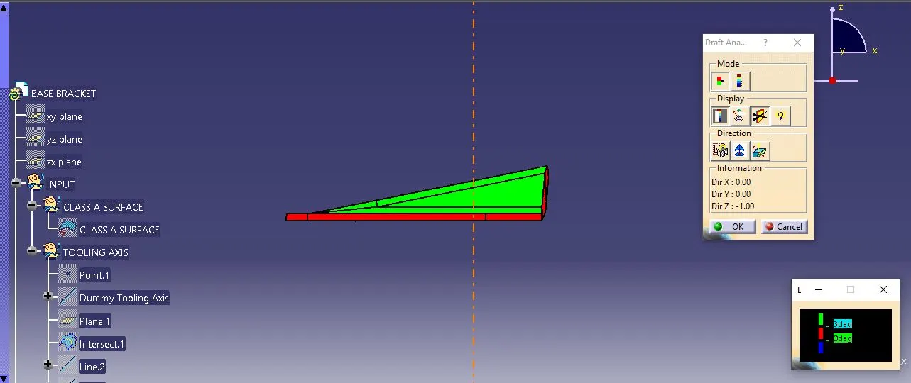
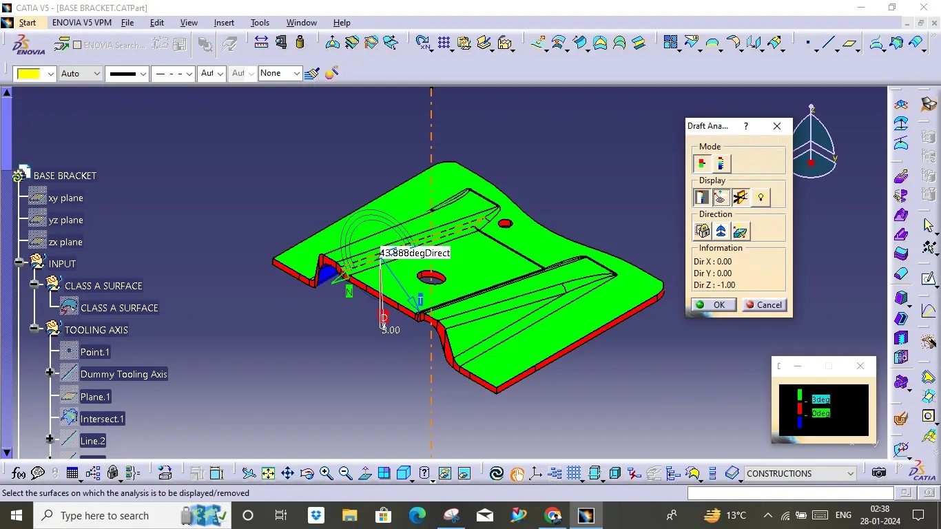
STEP II: DRAFT ANALYSIS FOR CLASS-A SURFACE
After creating the tooling axis we analyzed the draft angle of the given class-A surface. In this step we take the tooling axis as a reference for operation. With this analysis we can check whether the draft angle of a given class-A surface needs to be changed or not. The draft angle should be at least 3 degrees.
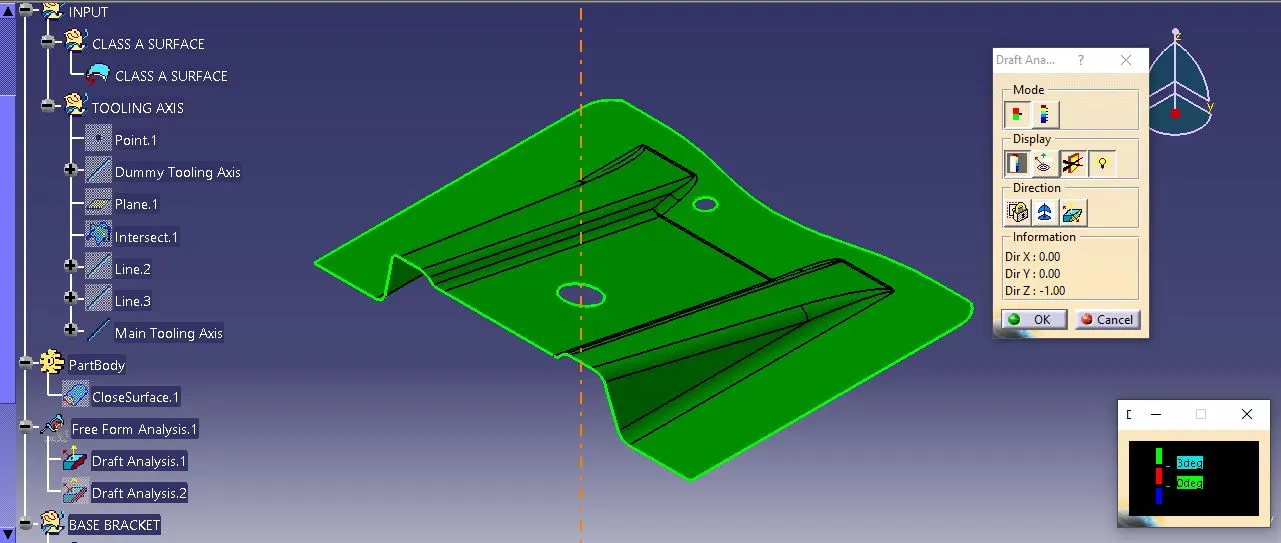
STEP III: CLASS-B SURFACE
In this step we are creating class-B surface. A surface below a certain thickness, which is the thickness of the material from the Class-A surface, is known as the Class-B surface.
To create a class-B surface we define the class-A surface in different color codes for each individual part for easy understanding.
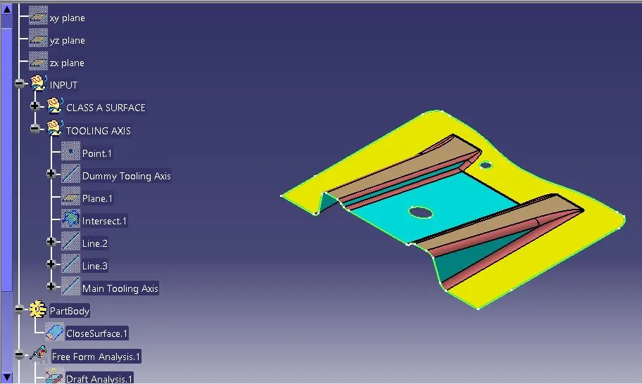
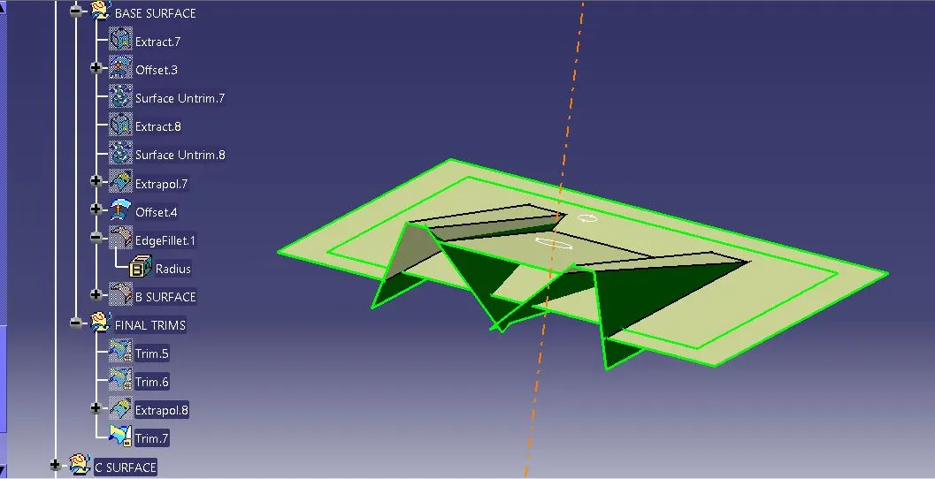
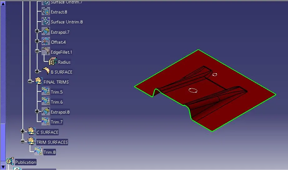
First we create the ribs, for this we first extract the class-A surface at a certain distance of 2.5 mm. After that we untrim the surfaces and then extrapolate to a distance of 10mm and then we use the trim command to get the desired shape of the object. Next we create the base surface with these commands. And finally we trim these surfaces to get the class-B surface.
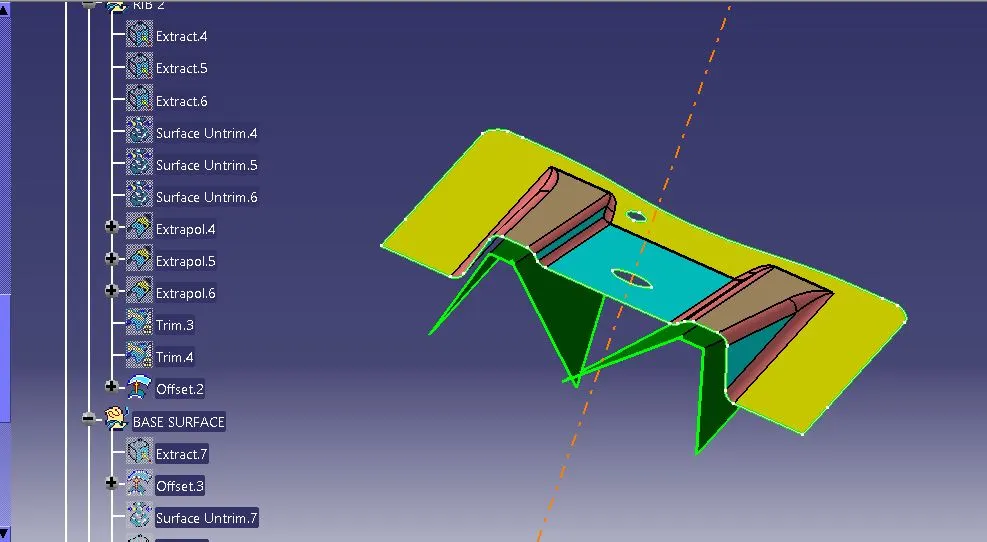
STEP IV: CLASS-C SURFACE
A surface that join class-A and class-B surface is known as class-C surface.
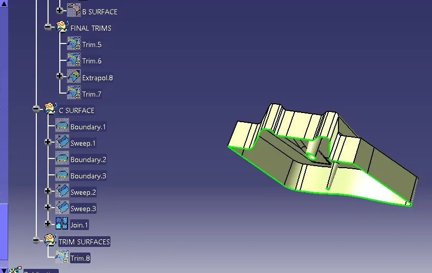
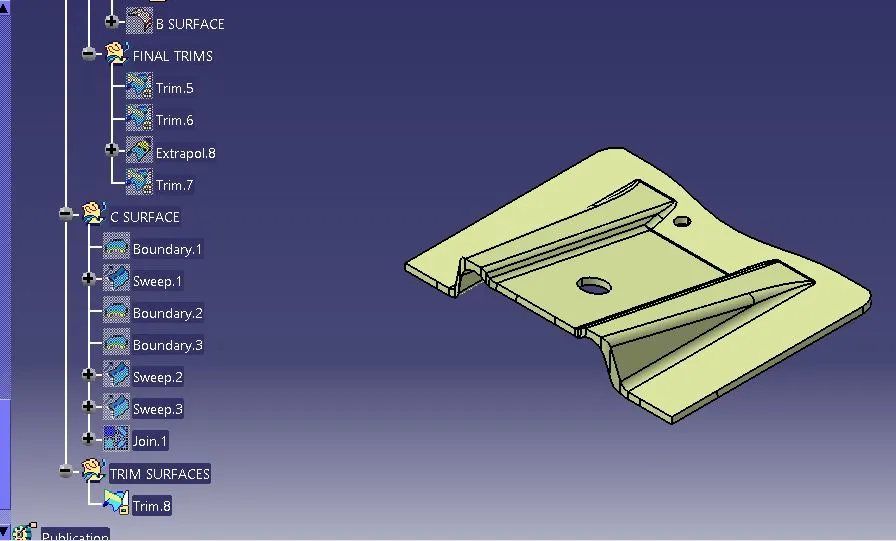
To create a class-C surface, we define the boundary of the class-A surface and then we create the connecting surfaces using the sweep command. Next we join the class-A and the connecting surfaces. We trim the class-B surface from the newly formed class-A surface to get the class-C surface.

STEP V: CLOSE SURFACE
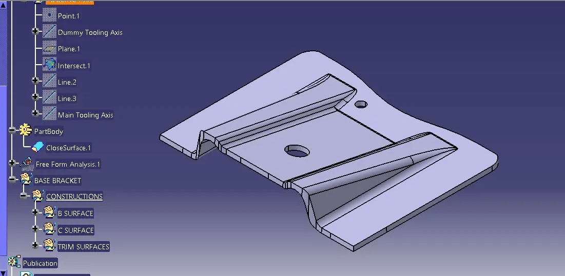
This is the final step of this base bracket design. After creating the class-C surface we use the close surface feature to get a solid body from the surface. We then analyze the draft to justify the model.
CONCLUSION:
Finally we perform draft analysis to justify the model. For this analysis the main tooling axis is taken as a reference and the minimum draft should be 3 degrees.