Week 9 - Challenge 1 - Base Bracket Design
CHALLENGE 10 BASE BRACKET DESIGN
AIM- Create the Base Bracket Plastic component through the given Class-A surface. To begin with, the tooling axis for the given Class-A Surface should be created meeting the requirements of the draft angle and at the end perform the Draft analysis on the model.
INTRODUCTION-
CLASS A SURFACE – The outermost skin of a part model which is visibly aesthetic surface/ free-form surface having an optimal shape & high surface quality. Design engineer with help of class A Surface create class B surface & class C surface.
CLASS B SURFACE- A surface below the Class A surface is created by design engineer to give a desirable thickness. This surface is also known as engineering surface.
CLASS C SURFACE- A surface that join Class A Surface & Class B surface.
METHODOLOGY
1) TOOLING AXIS
2) DRAFT ANALYSIS
3) CLASS B SURFACE
4) CLASS C SURFACE
5) CLOSED SURFACE (SOLID MODEL)
1) TOOLING AXIS
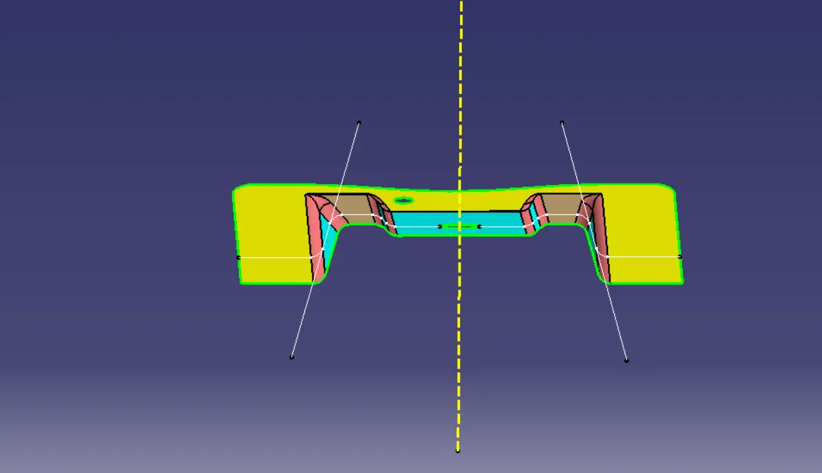
· First, we check all the three directions in X, Y, Z & check for suitable for the tooling axis. This case, Z Direction is the suitable tooling axis to create.
· Create a point by using circle/ellipse. Then generate a line point-direction to Z-Direction.
· Generate dummy tooling axis line by point-point direction.
· Intersect the YZ plane of the axis system by intersection command. Intersection line is generated.
· Create a bisecting line with help of dummy tooling axis line & select the point. A final tooling axis is generated.
1) DRAFT ANALYSIS
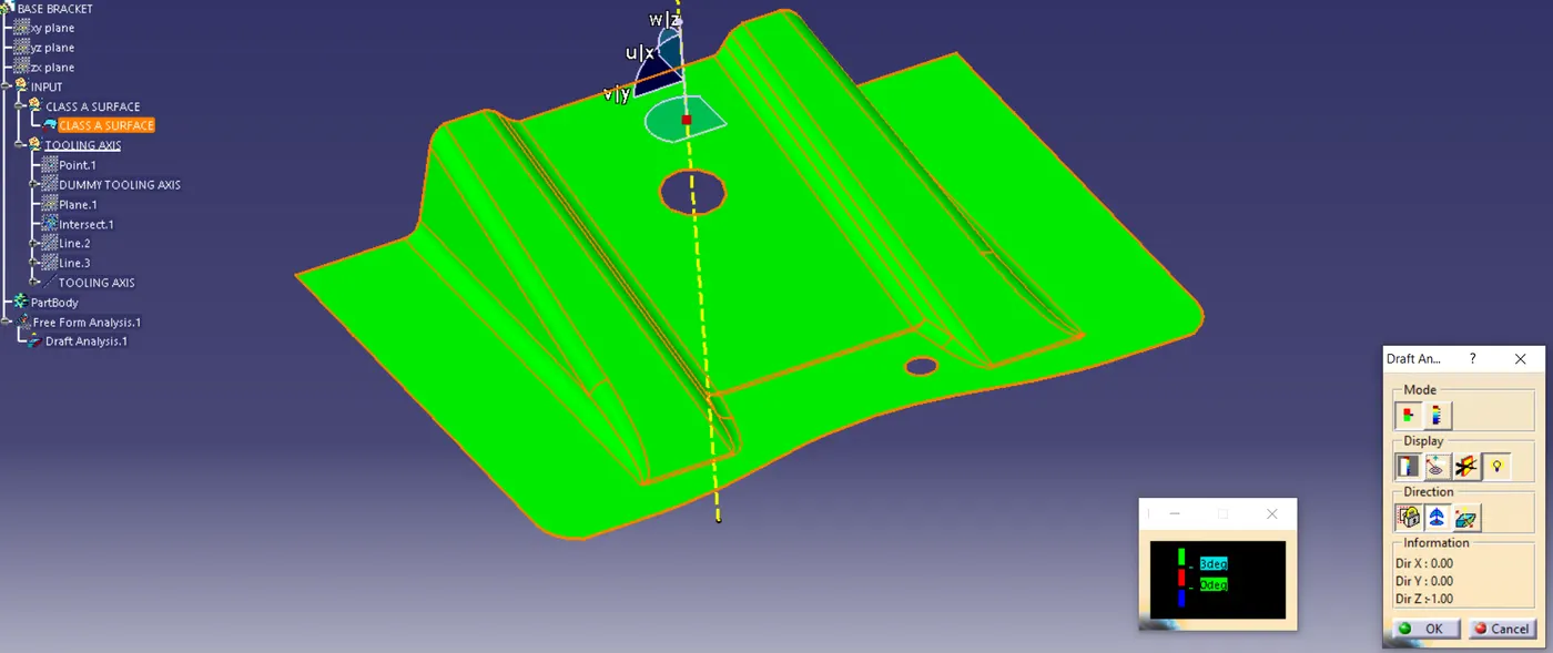
· Go to insert <analysis < feature draft analysis.
· Align the compass with the tooling axis.
· Click on the surface & see the surface within the permissible limit of the draft values.
· The surface should be green & in the column proper value (3deg) should be inserted.
1) CLASS B SURFACE
(i) RIB 1 & RIB 2
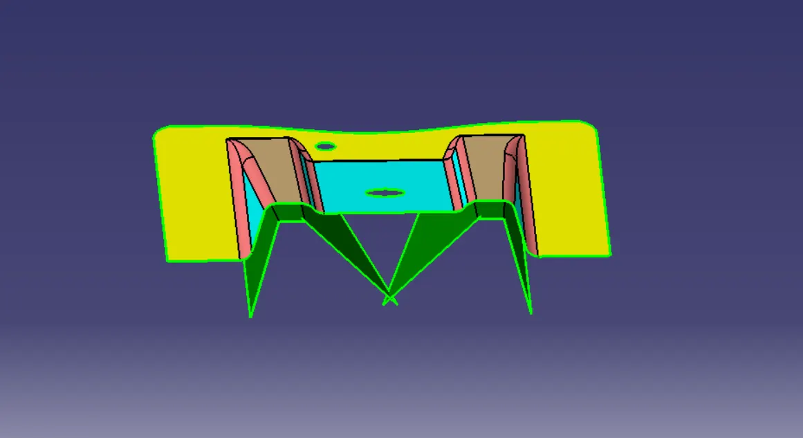
· Extract the rib surface for rib 1 & rib 2 respectively.
· Use un-trim command to un-trim the surface.
· Extrapolate one surface at a time.
· Trim the surface to create desired shape.
· Offset it down by 2.5 mm thickness.
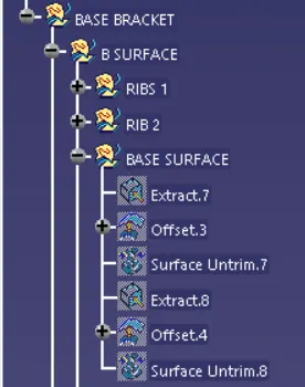
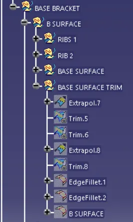
(i) BASE SURFACE
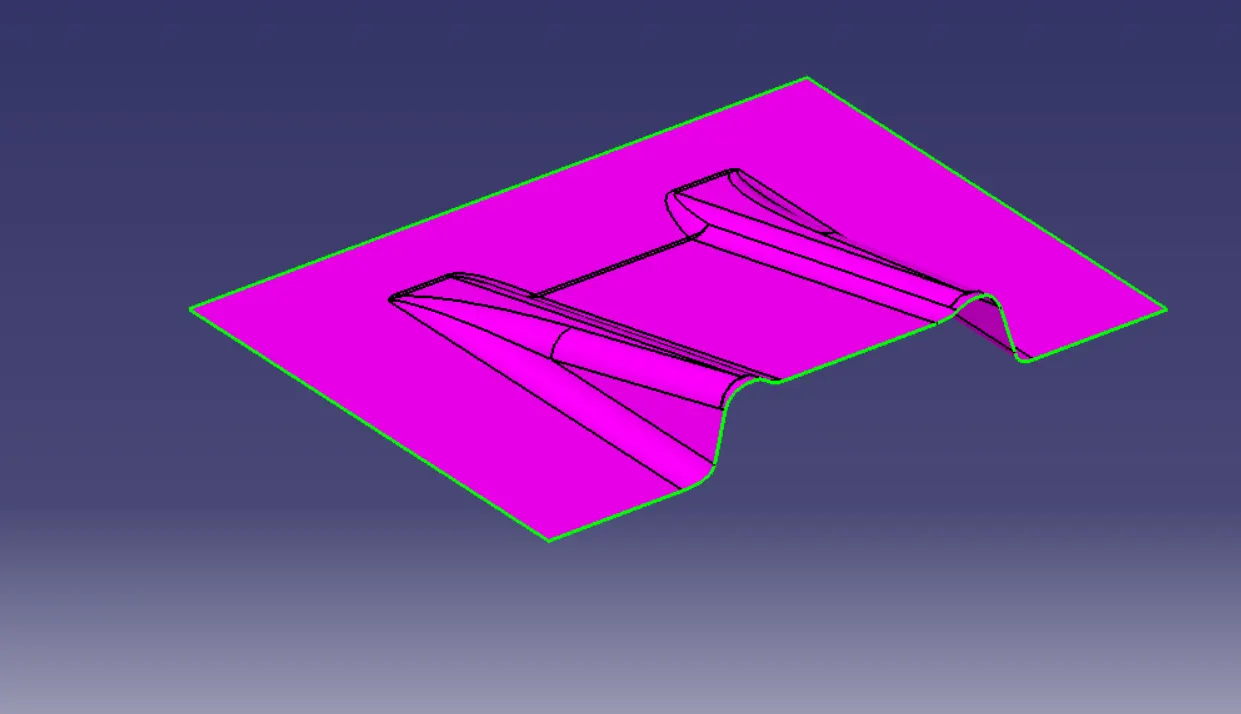
· Extract the slant surface & flat surface simultaneously.
· Un-trim the surface one at a time respectively (for both surface).
· Extrapolate the surface one at a time respectively (for both surface)
· Trim the surface to create the desired B Surface.
· Offset downward direction by 2.5 mm thickness.
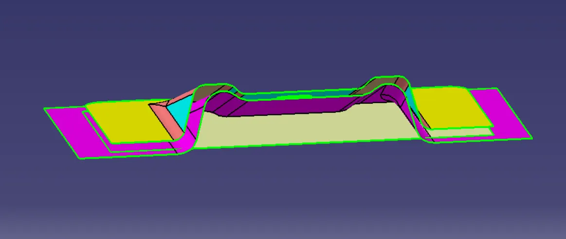
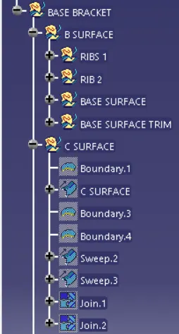
1) C SURFACE
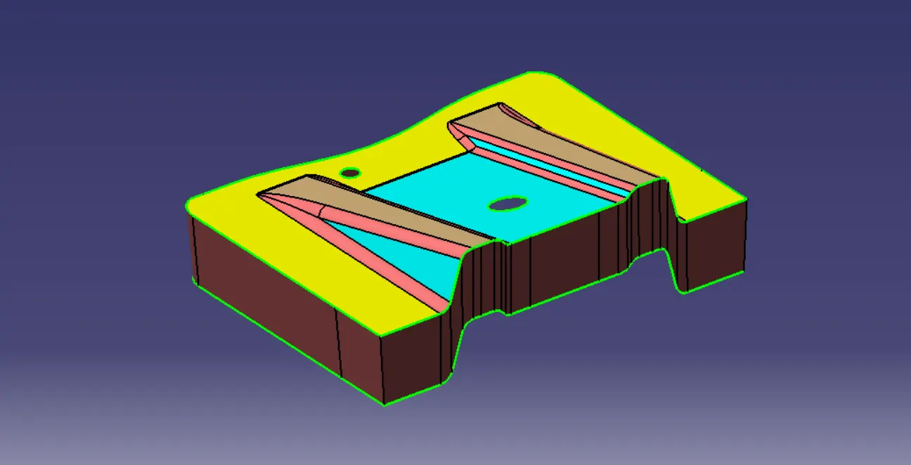
· Extract the boundary from the boundary command from Class A surface.
· Use sweep command on the boundary at angle of positive 3 degree. It will generate the C Surface.
· Extract the boundary of the holes on the Class A Surface, then use sweep command to generate the C surface in the holes.
· At last, join the Class A Surface & C Surface together by join command.
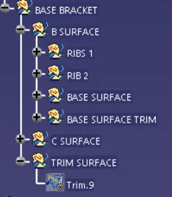
· Unhide the B Surface. Trim the B Surface & C Surface.
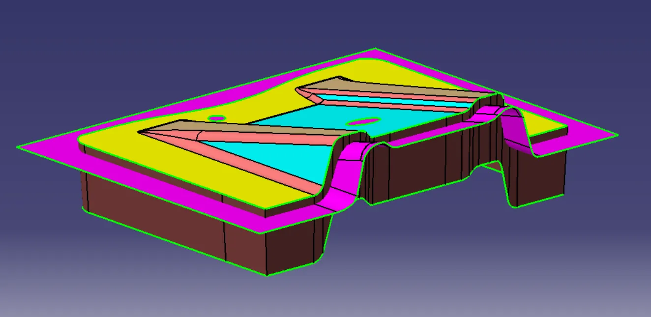
1) CLOSED SURFACE (SOLID MODEL)
· Go to mechanical design, define the part body tree.
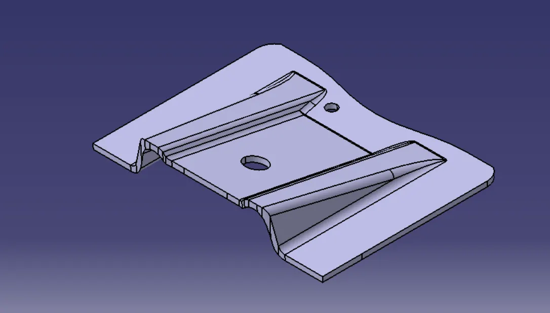
· Use the command closed surface & select the last trim section.
· Converted to solid model.
TREE FEATURES
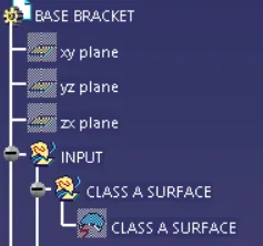
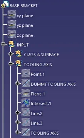
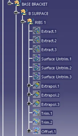
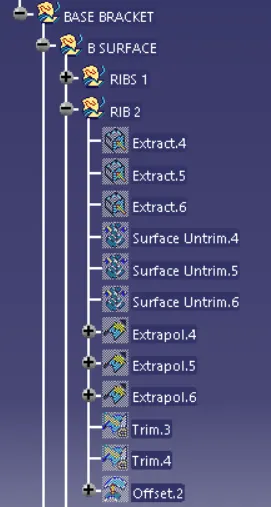
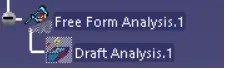
DRAFT ANALYSIS
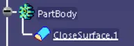
CLOSED SURFACE
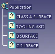
PUBLICATION
CONCLUSION- All instruction has been followed to create the base bracket accordingly.