Week -2
AIM-
1) Make a Simulink model of Doorbell using solenoid block.
2) Use a thermistor to sense the temperature of a heater & turn on or turn off the fan.
1) Make a Simulink model of Doorbell using solenoid block.
ABOUT-
SOLENOID- A solenoid is a device comprised of a coil of wire, the housing and a moveable plunger (armature). When an electrical current is introduced, a magnetic field forms around the coil which draws the plunger in.
In a solenoid, the core material is ferromagnetic, meaning that it concentrates magnetic lines of flux. This increases the inductance of the coil far beyond the inductance obtainable with an air-core coil of the same dimensions and the same number of turns. When current flows in the coil, most of the resulting magnetic flux exists within the core material. Some flux appears outside the coil near the ends of the core; a small amount of flux also appears outside the coil and off to the side.
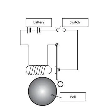
FIGURE 1
Basic components is used to generate door bell with solenoid are as follows-
- BATTERY
- SWITCH
- SOLENOID
- BELL WITH PLUNGER
BLOCK USED-
1. PULSE GENERATOR- Pulse generator is a time interval to control the switch.
2. SIMULINK-PS CONVERTER – This convert Simulink system to physical signal to the system/model.
3. BATTERY- Battery is used to give the power supply.
4. SPST SWITCH- This control the flow of current through battery.
5. SCOPE- To view the plot of time interval, velocity and position of the hammer.
6. PS-SIMULINK CONVERTER- This convert physical signal system to Simulink system to the system/model.
7. ELECTRICAL REFERENCE- This system is earthing/grounding for all the electrical system in the model.
8. MECHANICAL TRANSLATIONAL REFERENCE- To ground all the mechanical blocks.
9. SOLVER CONFIGURATION- To define the solver setting to do the simulation of the model.
10. SOLENOID- To generate the electromagnetic effect which attract the hammer towards the bell.
11. IDEAL TRANSLATIONAL MOTION SENSOR- This devices convert the variable measured between the two mechanical translational nodes into a control signal proportional to velocity and position.
MODEL CONSTRUCTION-
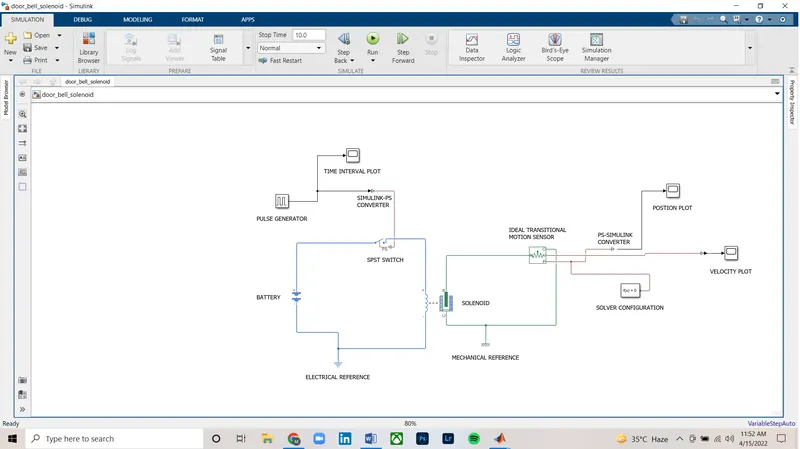
FIGURE 2
EXPLAINATION-
The above circuit diagram of the door bell requires block component that is design for the system/model for the simulation to perform.
- At first, ‘solenoid block’ and ‘battery block’ represent the solenoid model and battery model respectively in the library browser.
- The ‘SPST switch’ is connected to the battery model that provide the physical signal by ‘SIMULINK-PS CONVERTER’ through pulse generator.
- The battery model is connected to electrical reference block which is grounding of the system/model.
- In solenoid and ideal translational motion sensor both are having ‘R’ and ‘C’ ports. They are being connected to C-C port and R-R Port. In ideal translational motion sensor these ports are mechanical translational conserving port which monitor the motion of the plunger in the solenoid. This block represents the given output ‘V’ velocity and ‘P’ position of the plunger. So ‘P’ output is needed (i.e ‘P’ port is the physical signal output).
- The solenoid block is connected to the mechanical reference block.
- In ideal translational motion sensor the ouput port ‘P’ is connected to the scope by ‘PS-SIMULINK CONVERTER’, additional to that a solver configuration is also connected to the ‘P’ output port signal to do solving equation in the physical signal.
- In simulating the system/model, physical signal is provided by pulse generator through switch which generate continuous square pulse.
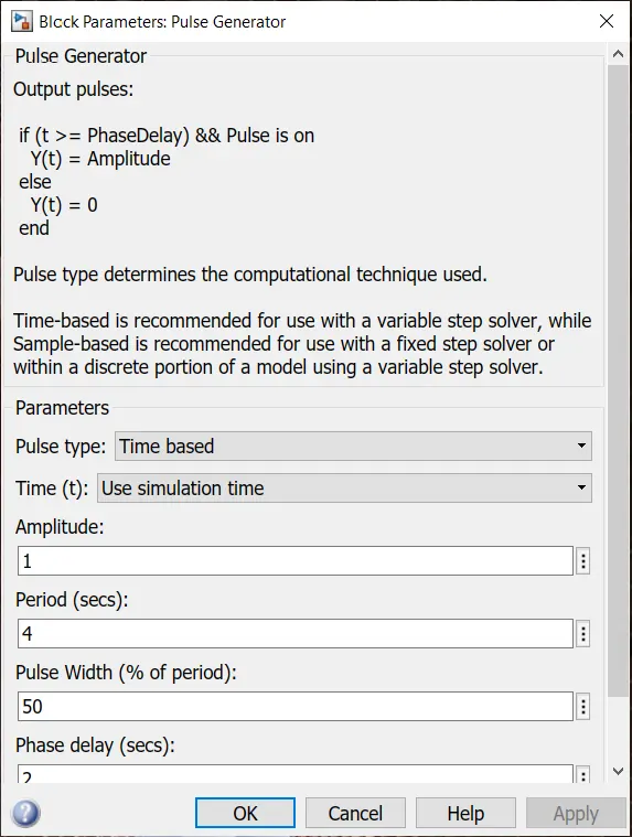
FIGURE 3
- The above figure 2 has been configure the parameter as mentioned in the question, so the value of period(secs) has been given 4, pulse width(% of period) is given as 50, amplitude is set as default value 1 and phase delay(secs) is 2.
- TIME VS AMPLITUDE
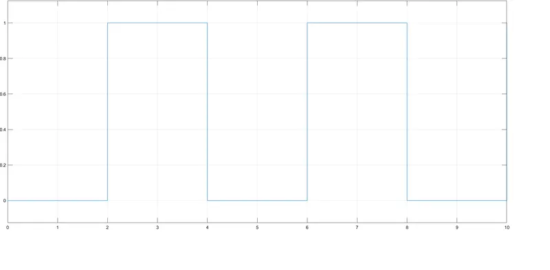
FIGURE 4
The above figure 3, shows the time vs amplitude plot
x-axis = time
y-axis = amplitude
The initial pulse which is generated will be ‘0’(zero) for 2 seconds(phase delay=2), at 2 seconds the pulse will amplitude from ‘0’ to ‘1’(i.e amplitude=1) and pulse width is half of the period (pulse width=50). The next 2 seconds of the pulse will be at ‘1’ (i.e amplitude=1) then later it will come to ‘0’(zero) at 4thseconds. This is the complete one cycle of the pulse(period=4). This same phase is repeat again in the simulation as is it set to ‘stop time=10s’. A scope is connected to the pulse generator to analyze the pulse modulation which is generated.
- This amplitude is zero then the switch is in open circuit at the initial starting 2 seconds as the amplitude reaches to 1 the switch is in closed circuit. The objective to check the change in position of the plunger as per the opening and closing of the switch which is provided by the pulse generator (i.e process mentioned in point no.9).
- TIME VS POSITION
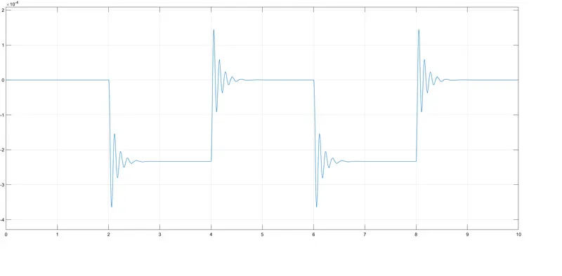
FIGURE 5
From the above figure, the initial position of the plunger starts from ‘0’(zero) from the pulse generator block, at ‘2’ pulse is generated and the position of the plunger is changing at the time 2seconds when the amplitude reaches to ‘1’. Again when the amplitude reaches to ‘0’(zero), the position of the plunger reaches to initial position.
- TIME VS VELOCITY
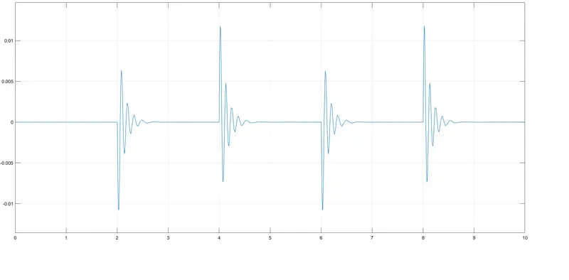
FIGURE 6
From the above figure, the initial velocity starts from ‘0’(zero) from the pulse generator block, at 2 velocity increases on 2 seconds and slowly it is diminishing linearly and comes to the initial velocity to ‘0’(zero). It again repeat the same process the same way.
CONSLUSION-
Door bell with solenoid has been simulated and the result is satisfactory.
2) Use a thermistor to sense the temperature of a heater & turn on or turn off the fan
BLOCK USED-
1. THERMISTOR- A thermistor is a resistance thermometer, or a resistor whose resistance is dependent on temperature. The term is a combination of “thermal” and “resistor”. It is made of metallic oxides, pressed into a bead, disk, or cylindrical shape and then encapsulated with an impermeable material such as epoxy or glass.
There are two types of thermistors: Negative Temperature Coefficient (NTC) and Positive Temperature Coefficient (PTC).
2. Negative Temperature Coefficient (NTC)- In NTC thermistor, as the temperature increases, resistance decreases. Conversely, as temperature decreases, resistance increases.
3. Positive Temperature Coefficient (PTC)- In PTC thermistor, as the temperature increases, resistance increases. When temperature decreases, resistance also decreases.
RESISTER- The resistor is an electrical component that limits or regulates the flow of electrical current in an electronic circuit. Resistors can also be used to provide a specific voltage for an active device such as a transistor.
The current through a resistor is inversely proportional to its resistance, and directly proportional to the voltage across it. This is the well-known Ohm's Law.
Where as,
R = V/I (resistor is inversely proportional to its resistance).
But
V= I*R (directly proportional to the voltage).
Resistors are used for many purposes. A few examples include limiting electric current, voltage division, heat generation, matching and loading circuits, gain control, and setting time constants.
5. SIGNAL BUILDER- To build the input temperature signal.
6. SCOPE- Analyze the plot of the signals generated by the model after the simulation process.
7. SIMULINK-PS CONVERTER- It converts the Simulink signal to physical signal.
8. CONTROLLED TEMPERATURE SOURCE- The Controlled Temperature Source block represents an ideal source of thermal energy that is powerful enough to maintain specified temperature difference across the source regardless of the heat flow consumed by the system. The temperature differential across the source is directly proportional to the signal at the control port S.
9. TEMPERATURE SENSOR- The temperature sensor block measure the temperature network. The device determine the temperature of differential measured between the two points without withdraw any heat. The port T report the physical signal of the temperature difference across the sensor.
10. THERMAL REFRENCE- To ground the thermal network.
11. ELECTRICAL REFERENCE- To ground the electrical network.
12. MECHANICAL ROTATIONAL REFERENCE- To ground the mechanical rotational parts.
13. SOLVER CONFIGURATION- To define the solver setting to do the simulation of the model.
14. BATTERY- Battery is used to give the power supply.
15. VOLTAGE SENSOR- To sense the threshold of the voltage.
16. SWITCH- To control based on the threshold value.
17. CONTROLLED VOLTAGE SOURCE- To regulate the voltage.
18. DC MOTOR- It is used to rotating the device.
19. IDEAL ROTATIONAL MOTION SENSOR- To sense the angular velocity and the angular displacement of a DC motor.
MODEL CONSTUCTION-
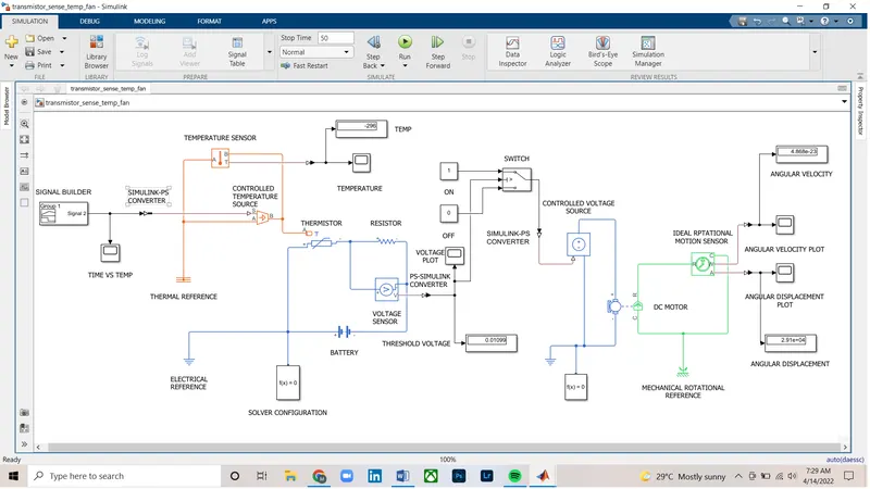
FIGURE 7
EXPLAINATION-
- The above model construction shown in the above diagram is the thermistor to sense the temperature of a heater & turn on or turn off the fan. To create the simple model requires the simple block component which are thermistor, resistor, battery, voltmeter and switch.
- At first, thermistor is used from the ‘THERMISTOR BLOCK’ and battery is used from ‘BATTERY BLOCK’, the positive terminal of the thermistor is connected to the positive terminal of the battery. The resistor is used from the ‘RESISTOR BLOCK’ which is connected to negative terminal of the thermistor to the positive terminal of the resistor. The negative terminal of the resistor is connected to the negative terminal of the battery. The ‘ELECTRICAL REFERENCE BLOCK’ is connected to the positive terminal of the battery, which gives the grounding to the electrical system in the model.
- Represent voltmeter as ‘VOLTAGE SENSOR BLOCK’ which is connected parallel to the resistor to measure the voltage across the component.
- Now, fan needs to switch ‘ON’ and ‘OFF’ which is operated by ‘CONTROLLED TEMPERATURE SOURCE BLOCK’. It gives the simplified heat temperature as output even though heat flow is more.
- Providing different temperature by ‘CONTROLLED TEMPERATURE SOURCE BLOCK’ requires some sort of temperature signals which is generated by ‘SIGNAL BUILDER BLOCK’. We can create a signal accordingly the way we want too or a given data temperature.
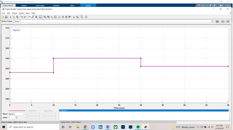
FIGURE 8
- The ‘SWITCH BLOCK’ is connected with ‘ON’ and ‘OFF’ (i.e constant block of value ‘1’ and ‘0’). The ‘V’ port in ‘SWITCH BLOCK’ is connected to the voltage sensor.
- The ‘CONTROLLED VOLTAGE SOURCE BLOCK’ is connected to the ‘SWITCH BLOCK’. The ‘CONTROLLED VOLTAGE SOURCE’ is connected to first half of ‘DC MOTOR BLOCK’ and in second half of ‘DC MOTOR BLOCK’ is connected with ‘IDEAL TRANSTIONAL MOTION SENSOR BLOCK’, at one side ‘R’ port is connected to the other side of ‘R’ port is connected with ‘DC MOTOR BLOCK’. Similarly, for port ‘C’ is connected with the other side of the port ‘C’ with ‘DC MOTOR BLOCK’.
- From the ‘IDEAL TRANSLATIONAL MOTION SENSOR’ port ‘W’ and ‘A’, angular velocity and angular respectively which is connected to ‘SCOPE BLOCK’ and ‘DISPLAY BLOCK’ to show the plot and the output value respectively.
- After constructing the whole model, final countdown starts that is simulation, ‘RUN’ the simulation and final output will show as plot or output value.
- TIME VS TEMP
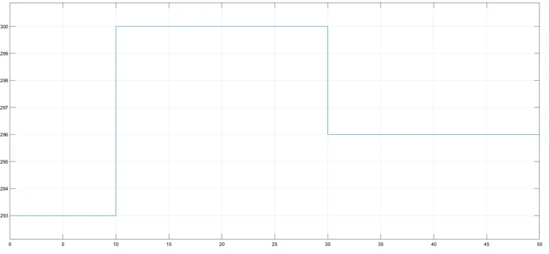
FIGURE 9
- TIME VS VOLTAGE
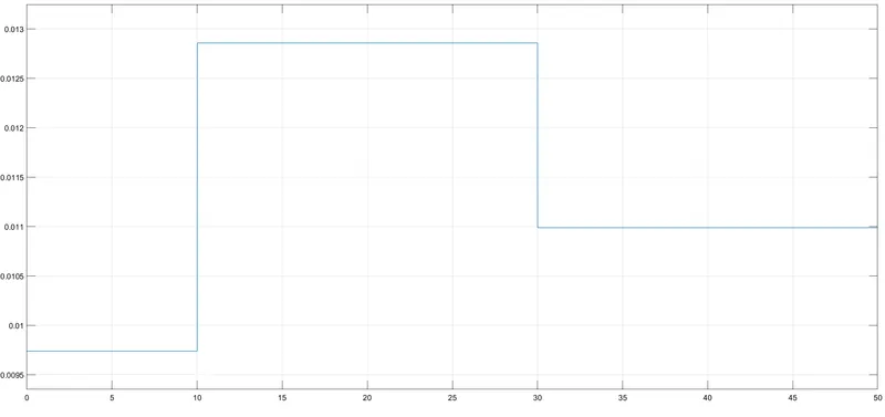
FIGURE 10
We noticed that from 0 to 10 seconds, when temperature is at 293K, the voltage is between 0.0095V to 0.01V, from 10 to 30 seconds, when temperature is at 300K, the voltage is between 0.0125V to 0.013V and from 30 to 50 seconds, when temperature is 296K, the voltage is nearly to 0.011V.
- As it is mentioned the fan should be ‘ON’, when the temperature is more than 298K then the above plot will be more than 0.011V and if the voltage is less than 0.011V then fan is ‘OFF’.
- TIME VS ANGULAR VELOCITY
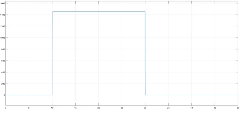
FIGURE 11
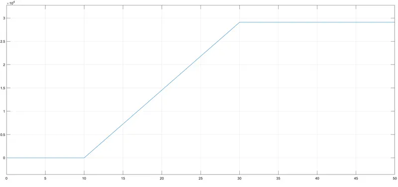
- TIME VS ANGULAR DISPLACEMENT
CONSLUSION-
Thermistor of a heater to turn on or turn off the fan has been simulated and the result is satisfactory.