Week 9 - Challenge 1 - Base Bracket Design
TITLE:- BASE BRACKET DESIGN
AIM:- To create the Base Bracket Plastic component through the given class-A surface and perform the draft analysis on the final component.
OBJECTIVES:-
- Creation of tooling axis for given class – A Surface.
- Creation of Class B and Class C surface
- Perform Draft analysis for given class A and final component.
TOOL USED:- CATIA V5
Introduction:- In this project, we are designing a base bracket using a given class A surface. The approach includes the creation of a tooling axis, Class B surface, and Class C surface keeping the given thickness of 2.5 mm.
CLASS A:- The following surface is given as the input for the component creation.
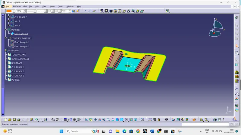
To continue the design first we need to create a tooling axis for the class A surface.
Draft Analysis for class A surface:-
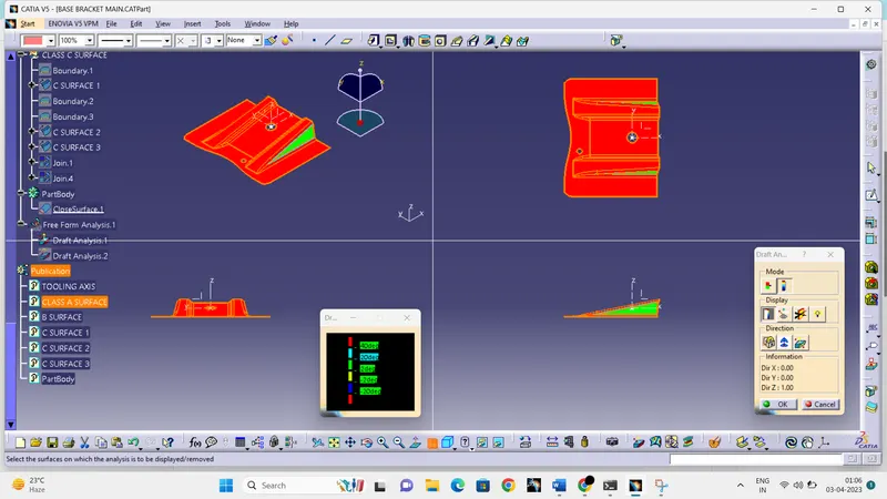
All the draft angles are more than 3 degrees in draft analysis.
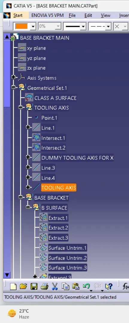
Creation of Tooling Axis:-
- First create an axis system in point 1.
- Create a sketch using the intersection command with class A surface and zy plane.
- Check all the portions of the sketch and create lines on the sketch portion which will probably not intersect the tooling line.
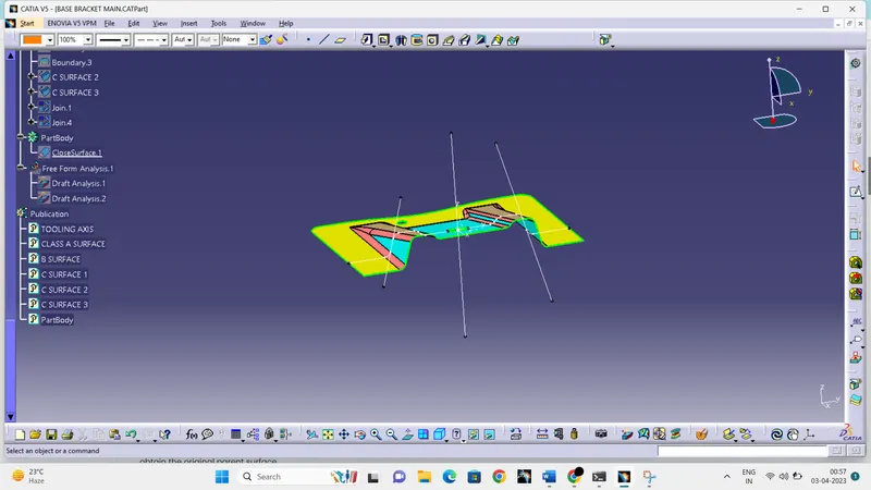
- Then create a bisecting line selecting the drawn lines and vertical dummy axis.
- Repeat the process with the zx plane and class A surface and create a dummy axis.
- Now create a bisecting line selecting both the dummy axis for x and y and point 1, resulted line is a final TOOLING AXIS FOR CLASS A.
Creation of Class B surface:-
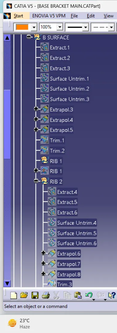
- Now for class B creation, extract the class A surface and untrimmed the surfaces.
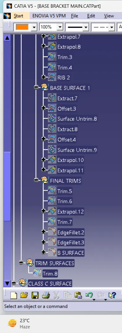
- Trim the surfaces according to the required class A surface.
- Now offset the surfaces with the given thickness.
- Create fillets for required edges.
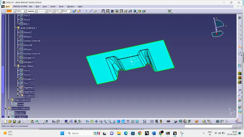
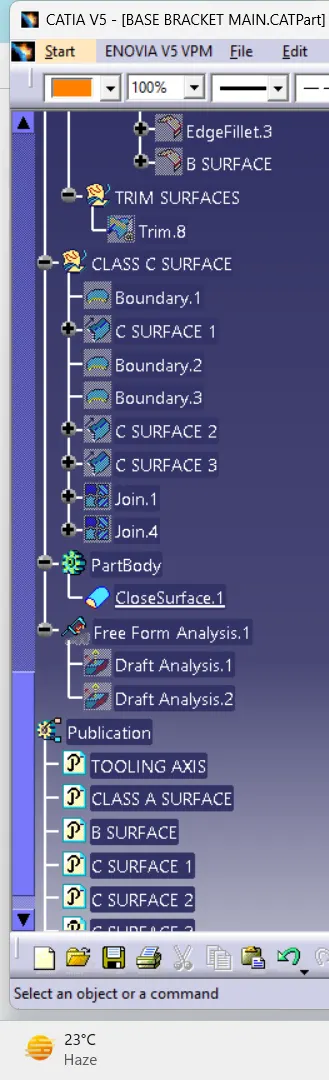
Creation of Class C surface:-
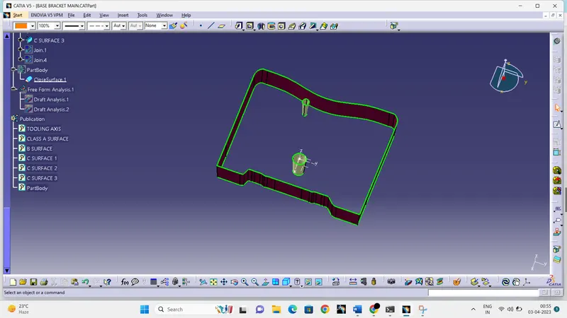
- Create a boundary of class A surface and use the sweep command to create the surface with a 3-degree draft angle.
- Join all the C surfaces.
FINAL TRIMS:-
CLASS C SURFACE + CLASS B SURFACE
- Finally trim the joined surface with the class B surface to get the final surface body of the component.
PART BODY:-
Use the close surface command in the part workbench to change the surface body into a closed surface to get the final component.
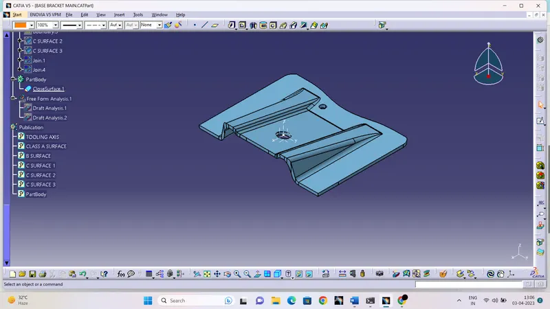
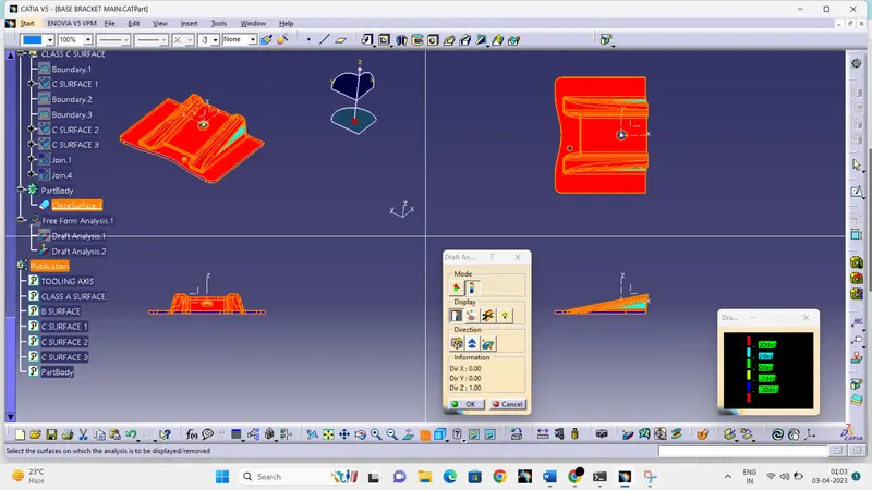
Draft analysis for the finalcomponent :-
For this analysis, the main tooling axis is taken draft reference.
The following results were obtained:-
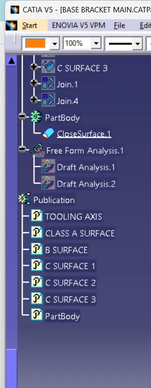
DESIGN TREE IMAGES :-