Week 9 - Challenge 3 - Bumper
WEEK 9 CHALLANGE 3
BUMPER DESIGN :-
AIM :- To create the bumper plastic component through the given Class A surface. To begin with, the tooling axis for the given Class-A Surface should be created meeting the requirements of the draft angle and at the end perform the Draft analysis on the model.
INTRODUCTION:- A bumper is a bar attached transversely in front of or behind a car body to prevent contact between an obstruction and the car body or to cushion the shock of collision between vehicles. The impact-bars have various sectional forms, from flat to round and from tubes to channels, and are composed of steel, wood or rubberized fabric. The attaching devices are sometimes yielding, sometimes rigid.
OBJECTIVE :-
- Creation of tooling axis for given class – A Surface.
- Creation of Class B and Class C surface
- Perform Draft analysis for given class A and final component.
DESIGN METHODOLOGY :-
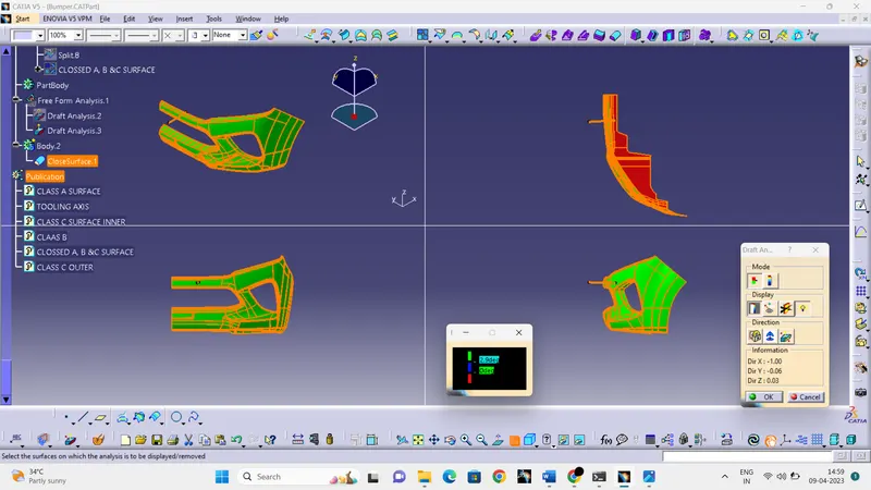
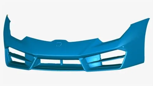
CLASS A:- Class-A surface means visible surface. It gives the aesthetic of the component which is created by the styling team and gives to the part design engineer to create the part with all engineering aspects.
Given surface is given as the Input data :-
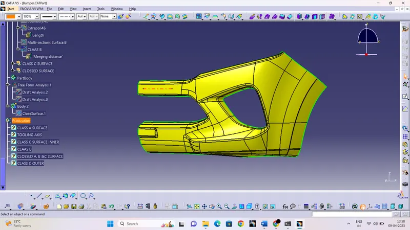
Creation of Tooling Axis:-
Tooling axis represents the opening and closing direction of mold and cavity in manufacturing of the component. A plastic product designer should consider the best tooling direction to cutdown the cost of the component very less.
- Check the best direction for tooling axis.
- We can find out the best tooling direction by cross checking all the three axes.
- Here we can find out that the best tooling direction for the pumper class-A surface is along x-axis direction.
- first look for the flat surface, and extract that surface and creat a point on that surface.
- Create a line , using point and surface .
- This line is a tooling axis line for class A.
Draft Analysis of Class A surface :-
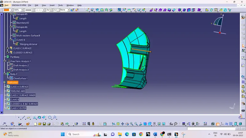
The Draft Analysis is a command enables you to detect if the part you drafted will be easily removed. This type of analysis is performed based on colour ranges identifying zones on the analysed element where the deviation from the draft direction at any point, corresponds to specified values.
Draft analysis is done after determining the tooling axis, draft analysis is used to check whether the minimum draft (3 degrees) is maintained or not.
The different colour shows the different draft angles :-
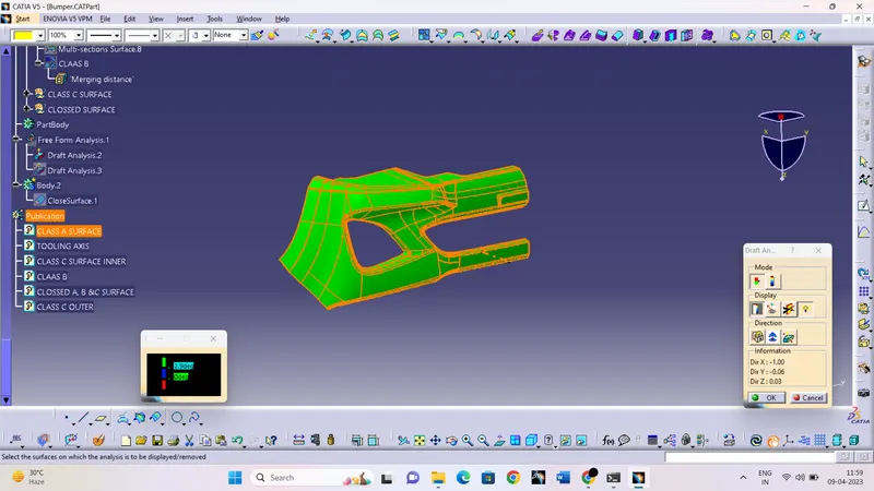
- Greeen colour shows the all the draft on surfaces are more than or equal to 3 degrees.
SURFACE B CREATION:-
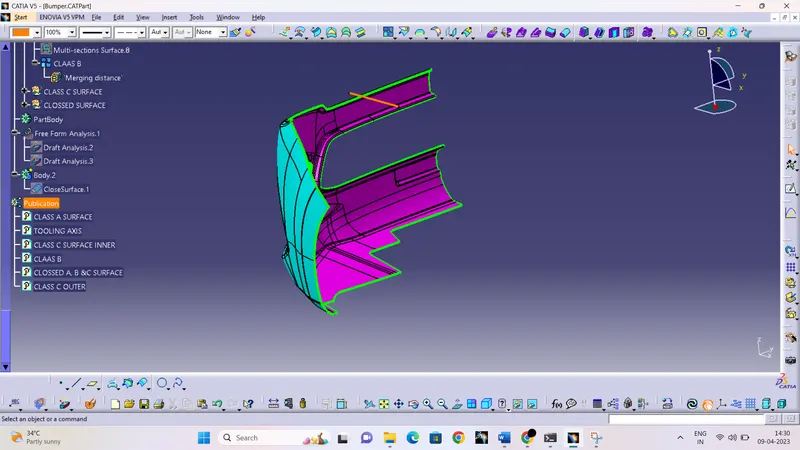
Class B surface is a offset surface from a class A surface at cerrtain thickness.It is the surface at which all the engineering features are mounted.
- offset the Class A surface at 3mm surface in inward direction.
- Check the continuity and patches in offset surafce.If the patches are present then we have to fill it manually by using different commands like JOIN,EXTRACT SWEEP ETC.
- To ensure the continuity of the Class-B surfaces check the boundary command to find out the boundary.
- Hence class-B surface creation is done.
- CIAN colour shows the class A surface and the purple colour shows the class B surface.
SURFACE C CREATION :-
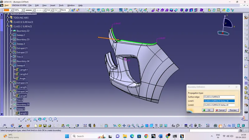
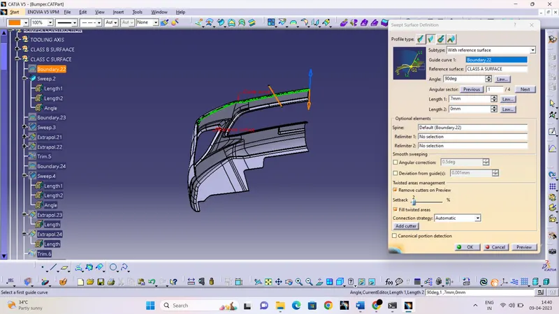
Surface that joins class-A and class-B surfaces is class-C surface. Class C is often specified for interior surfaces not readily visible, surfaces that will be covered by another part when assembled
- Since it is a complex surface we can not create boundaries and sweep it off at one shot.hence we have to divide it in smaller parts and sweep it in parts.
- Extrapolate and trim off the sweep surface corners at the required edges.
- Join the sweeps using the join command and the class-c surface is created.
Creating the final surface of BUMPER:-
- First step is to join the CLASS-A surface with CLASS-C surface.
- Then Trim the Joined surface with CLASS-B surface to achieve the final Bumper surface.
- Go to part design workbench and use close surface option to create a solid part body.
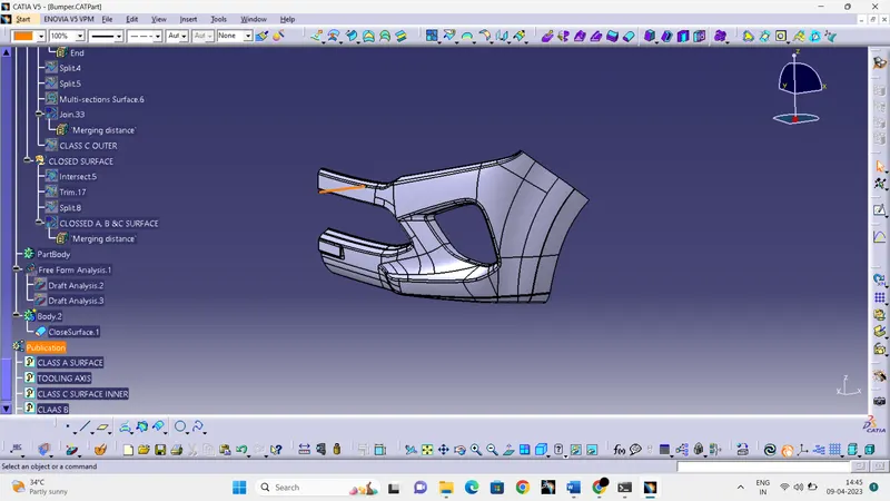
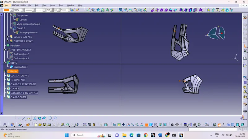
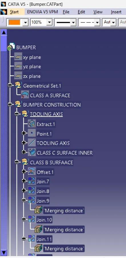
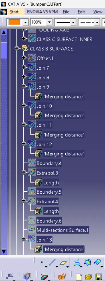
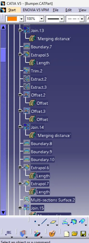
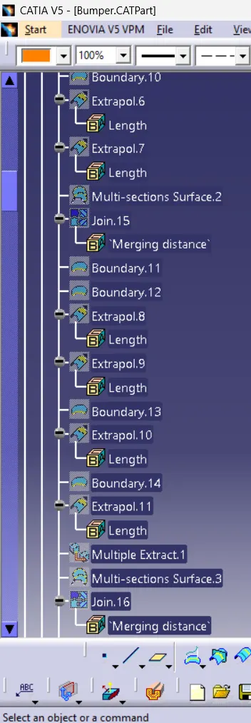
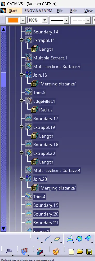
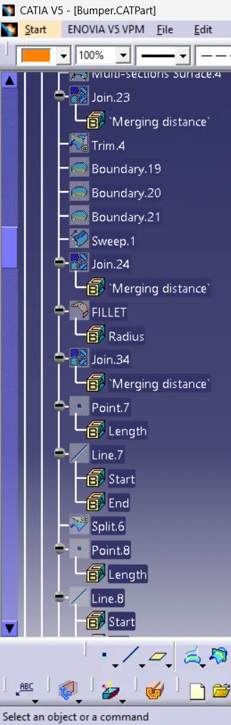
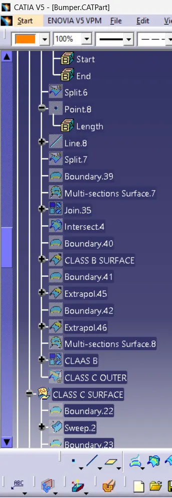
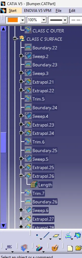
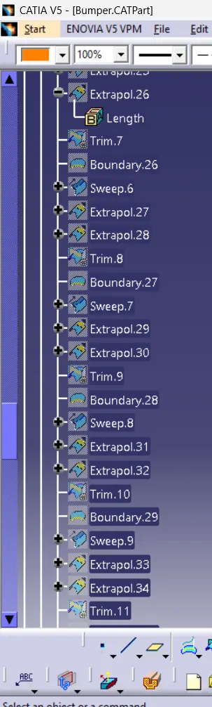
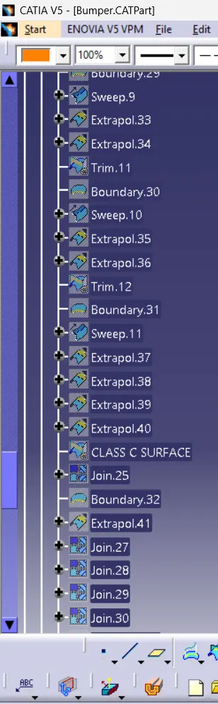
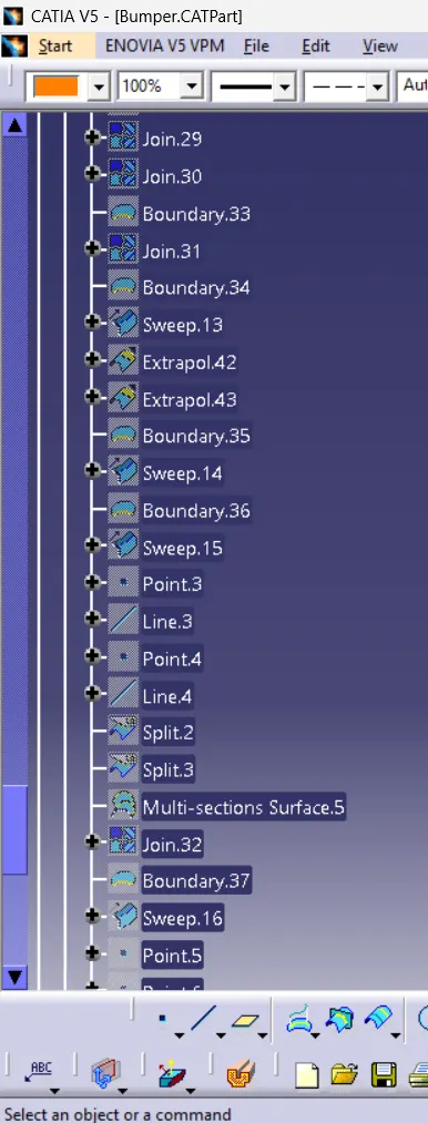
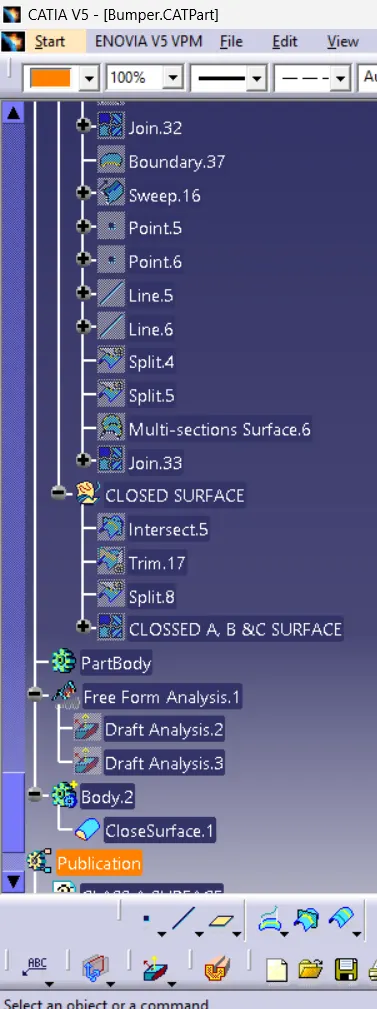
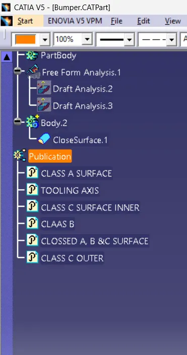
EXPANDED TREE STRUCTURE FOR THE GEOMETRICAL SET AND PRT BODY:-
DRAFT ANALYSIS OF FINAL COMPONENT :-