Week 10 - Challenge 3 - Door Trim Lower with Engineering Features
TITLE :- DOOR TRIM LOWER WITH ENGINEERING FEATURES
AIM:- Create the Door Trim Lower Plastic component through the given Class-A surface. To begin with, the tooling axis for the given Class-A Surface should be created meeting the requirements of the draft angle and at the end perform the Draft analysis on the model. Create the Heat Stakes and the locators considering the design rules for the door applique.
OBJECTIVES :-
- Creation of tooling axis for given class – A Surface.
- Creation of Class B and Class C surface
- Perform Draft analysis for given class A surface and final component.
- Adding heat stakes and locators to door applique.
- writing a detailed report on draft analysis result.
PROCEDURE FOR CREATION OF SOLID MODEL:-
- First check the given Class A surface that there will be no patches present it must be continuous surface.
Creation of Tooling Axis:-
- Check the Class A aurface for the best possible direction for tooling axis.
- Look for the flat surface or otherwise use the bisecting method to create the tooling axis.
- Extract the flat surface and create a point on that.
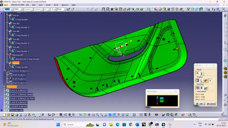
- Create a line in tooling direction and perform the draft analysis and check whether the Class A surface is clearing the minimum 3deg draft value.
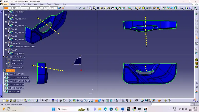
Draft Analysis of Class A surface:-
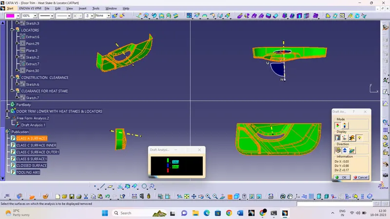
- Green colour shows that minimal 3 degree value is cleared by the Class A surface that means Tooling Axis is correct.
Creation of Class B surface:-
- Class B surface is the surface where all the engineering features are assembled.
- First offset the given Class A surface by given thickness value.
- Next, look for the patches in offset surface and we have to make it a continuous surface using different commands.
Creation of Class C surface:-
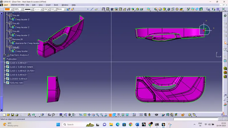
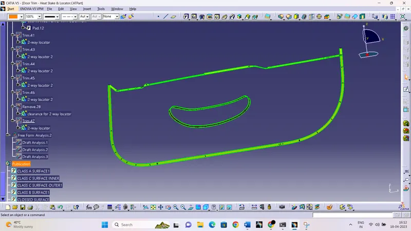
- Create a boundary on Class A surface and extrapolate it to intersect with class B surface.
FINAL TRIM OF CLASS A AND CLASS C SURFACE:-
- Now trim the class A and class c surface together.
- Finally trim the joined class A and Class C surface with Classs B to get the final surface.
Creation of Solid Body:-
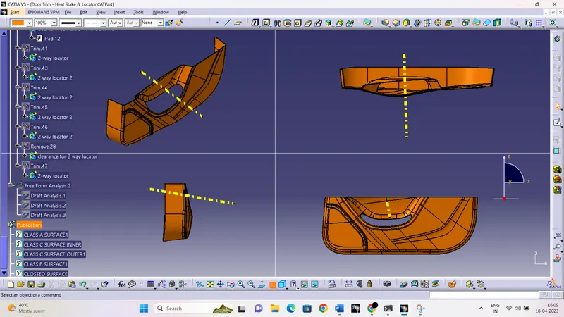
- In part workbench, using the close surface command make it a solid body.
Creation of 4-WAY locators :-
- Locators are used to restrain the motions to position the components at desired position.
- Position of component comes first before the fixation.
- We have to create the sketch for 4 way locators.
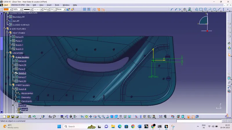
- Then we have to pad it and provide draft to the side faces.
- Now union trim with the main door panel.
- Every 4 way locator required clearance at base .
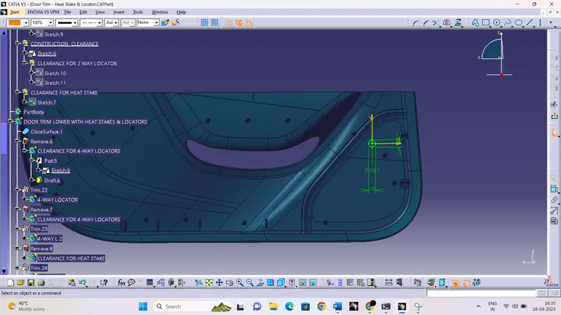
- Create a circular sketch and pad it and give the draft value according to the design rules.
- Then remove it with main door panel to give the clearance at base.
Creation of 2 WAY Locators:-
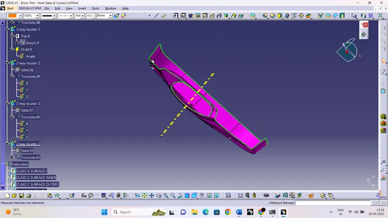
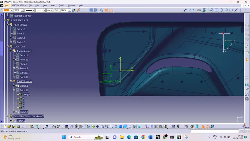
- Create a sketch for 2 way locator.
- and do the same process as we did for 4 way locators.
Creation of Heat Stakes:-
- After positioning comes a fixation so heat stakes are used to fix the components.
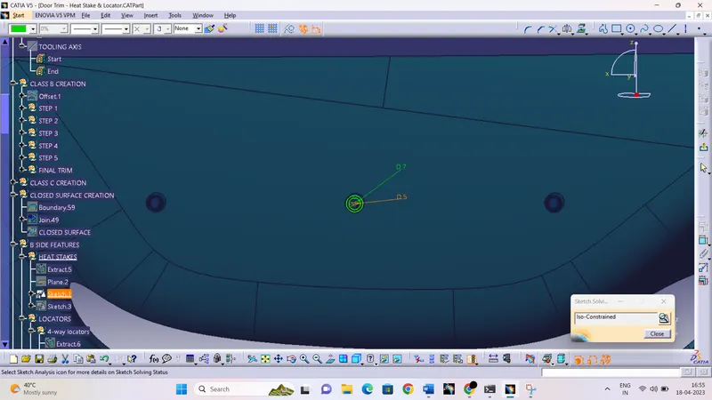
- Create a sketch for heat stake and give draft and union trim with main door panel.
- Clearance at base is required value should be 0.5mm each side.
FINAL COMPONENT WITH ENGINEERING FEATURES:-
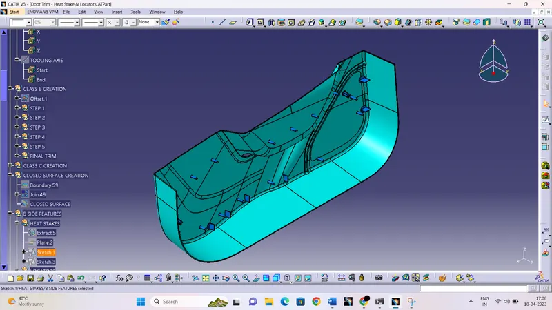
DRAFT ANALYSIS OF FINAL COMPONENT WITH ENGINEERING FEATURES:-