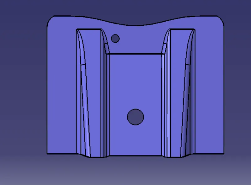
Week 9 - Challenge 1 - Base Bracket Design
BASE BRACKET DESIGN
Objective:
1. Create the Base Bracket Plastic component through the given Class-A surface.
2. Create the Tooling Axis.
3. Perform the Draft Analysis on Class-A Surface and final component model.
Software Used:
CATIA V5.
BASE BRACKET : CLASS A SURFACE
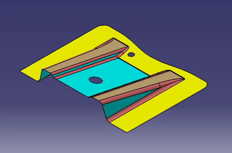
TOOLING AXIS
Tooling axis: The direction in which the mold or core and cavity opens is the tooling axis.
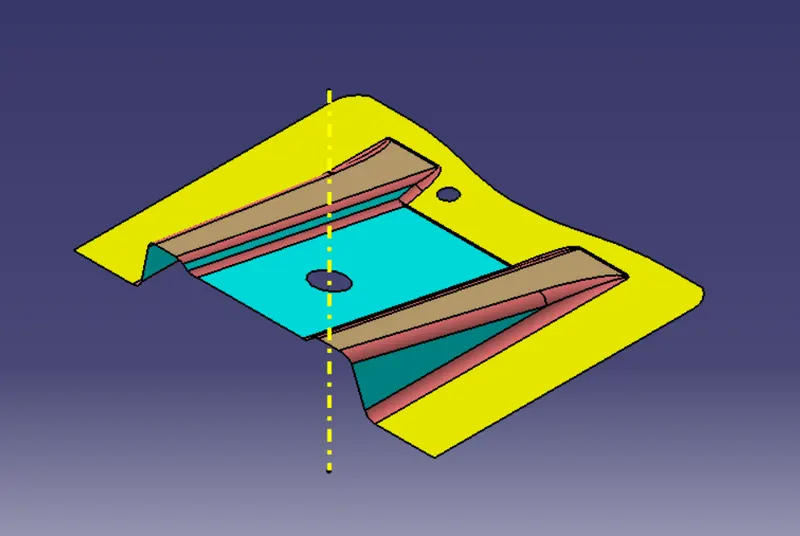
Steps to Create a Tooling Axis :
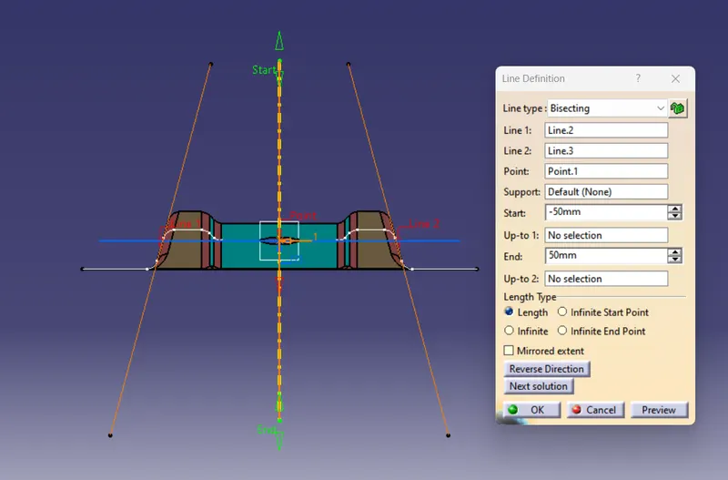
1. Firstly, Create a geometrical set name as "Tooling Axis" and then take 'Reference point' at the centre of hole created on a Surface.
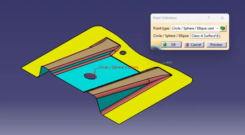
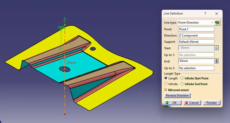
2. Create a 'Dummy Tooling Axis' by selecting the above created point and selecting Z-Direction.
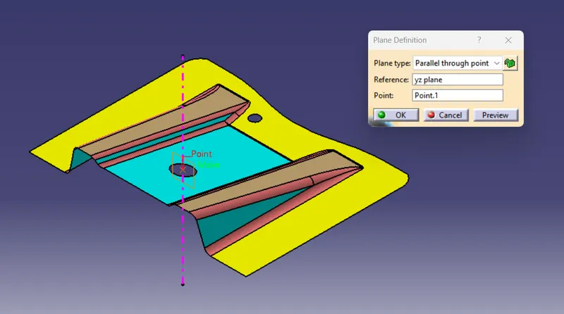
3. Take a 'YZ plane' on the created point parallel to tooling axis with zero offset to axis.
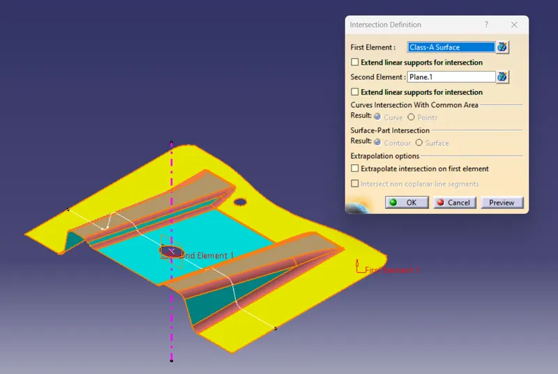
4. 'Intersect the Plane with the surface' to get the outline sketch of the surafce in YZ plane.
5. Create the line from point on the sketch oultine of inclined surafce inclined at an angle to the dummy axis.
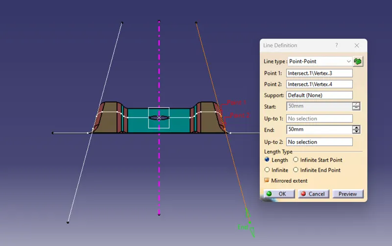
6. Bisect both the inclined line with the point to get the bisecting line as a Tooling axis and named as Tooling axis to be used for draft analysis.
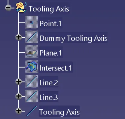
Tooling Axis : Tree Structure
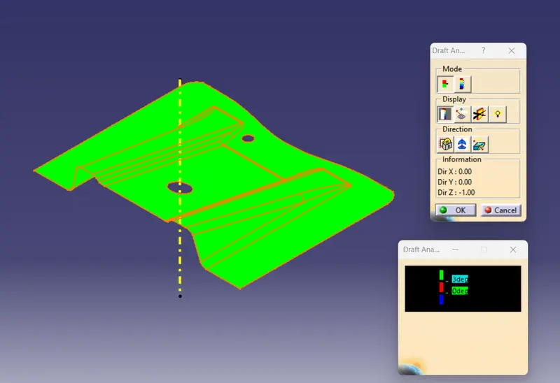
DRAFT ANALYSIS : CLASS A SURFACE
Draft : The purpose of providing angles or tapered face by draft is to remove the part from the mould with ease so that it is parallel to the direction of mould release.
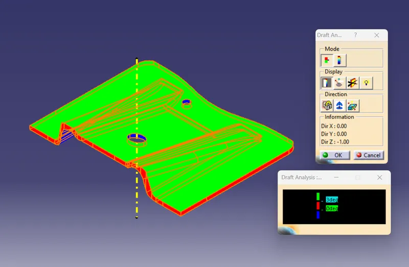
DRAFT ANALYSIS : SOLID COMPONENT
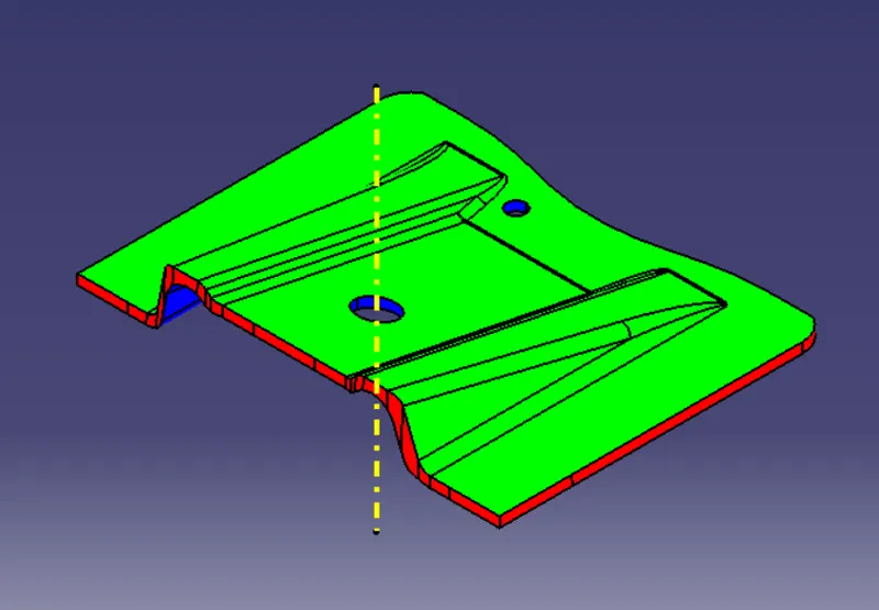
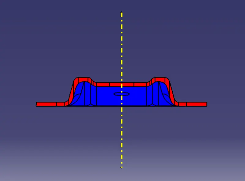
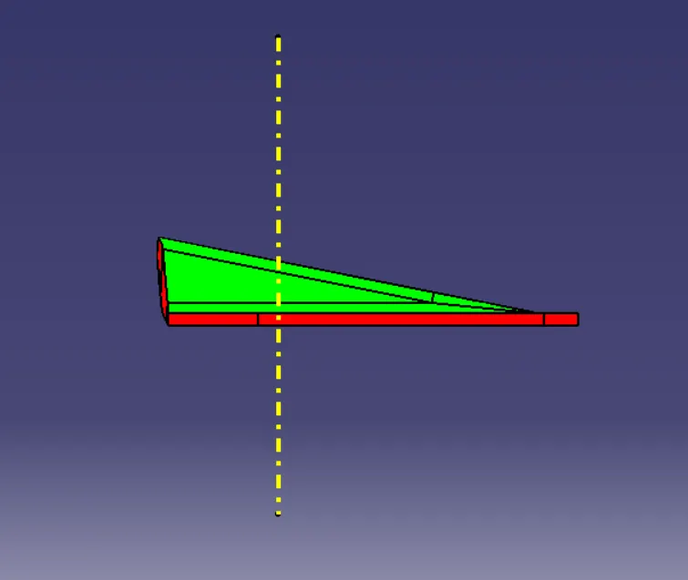
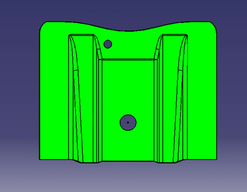
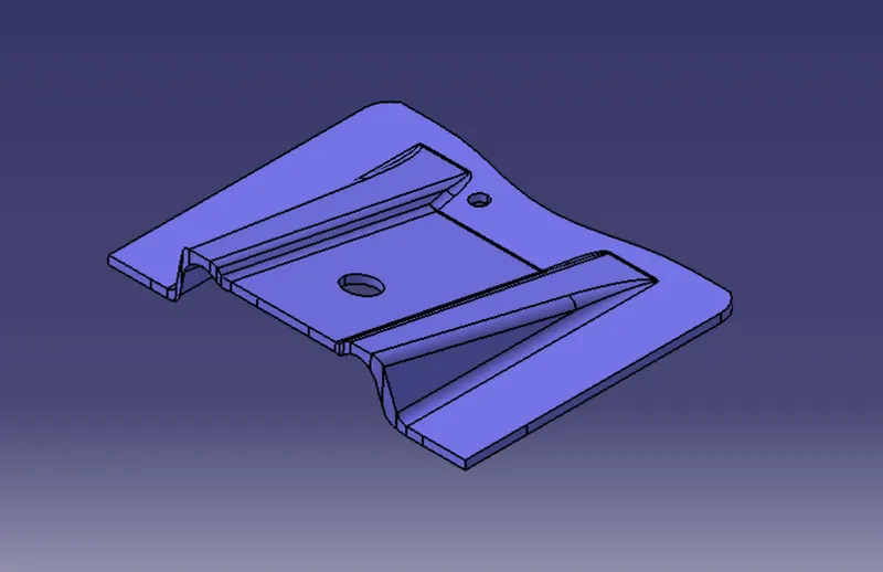
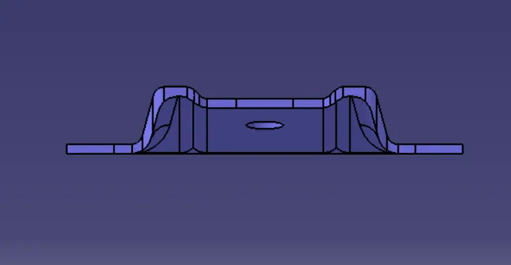
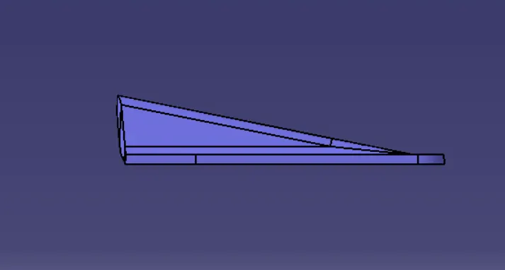
Differenet Views of Solid Component : With Draft
Isometric View
Front View
Side View
Top View
Steps for Draft Analysis :
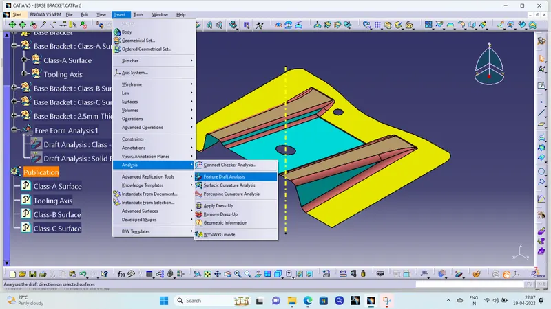
1. First go to the surface tab bar then click on Insert -> Analysis -> Fetaure Draft Analysis.
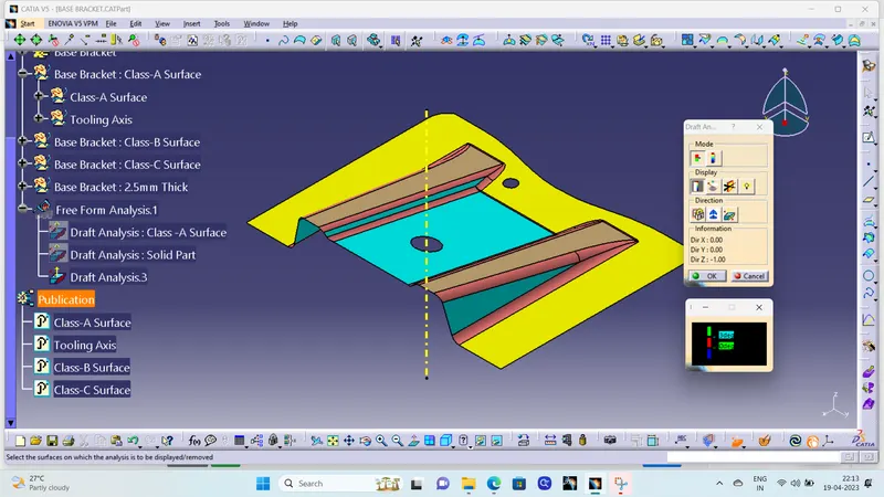
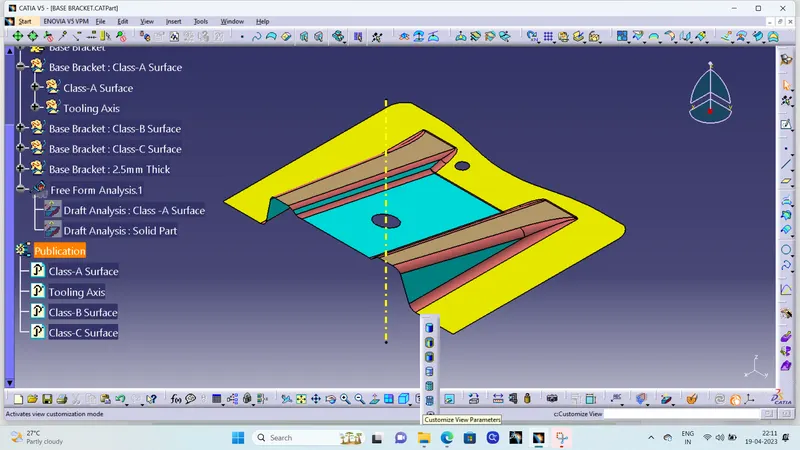
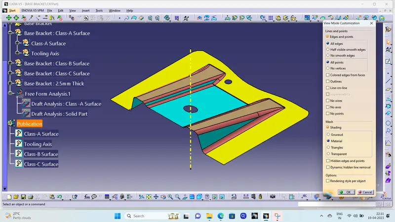
2. Then go to Customize View Parameters and check whether the material box under mesh is ticked or not. If not ticked click on the box and tick it for draft analysis.
3. Then, ensure in Draft Analysis Box, Mode is swicted to Quick analysis mode, Color scale Display should be on, select the compass to define the direction.
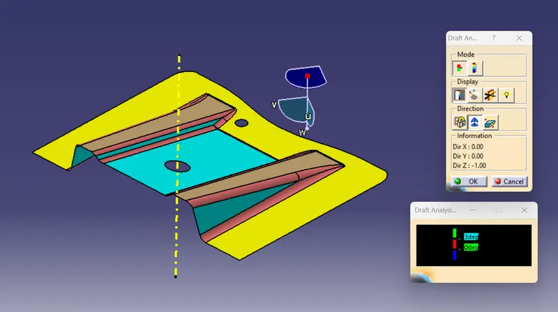
4. Drag the compass on the tooling axis for Draft Analysis then select the surafce or body to be draft analysed.
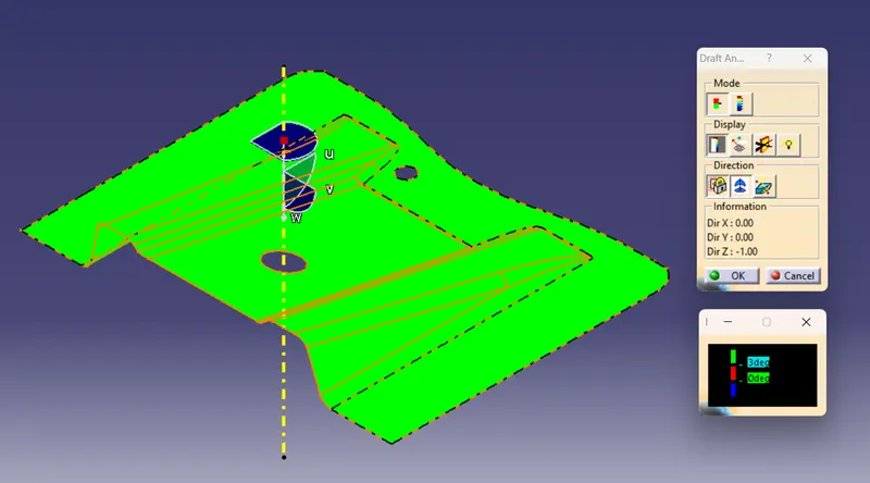
Note : Under Draft Analysis Color Display Dialog Box double click on the parameter tab and input the desired angle on which draft analysis to be perform.
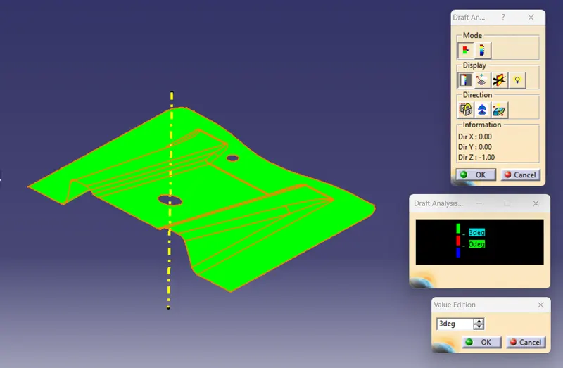
For this Model : Draft Angle is taken as 3 Degree.
- Green : Angle is more than 3 Degree.
- Red : Angle is less than 0 Degree.
- Blue : Draft in Reverse Direction to selcted direction.
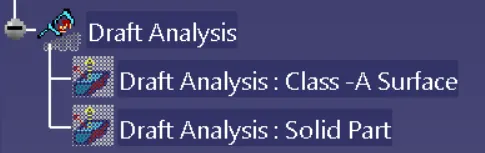
Draft Analysis : Tree Structure
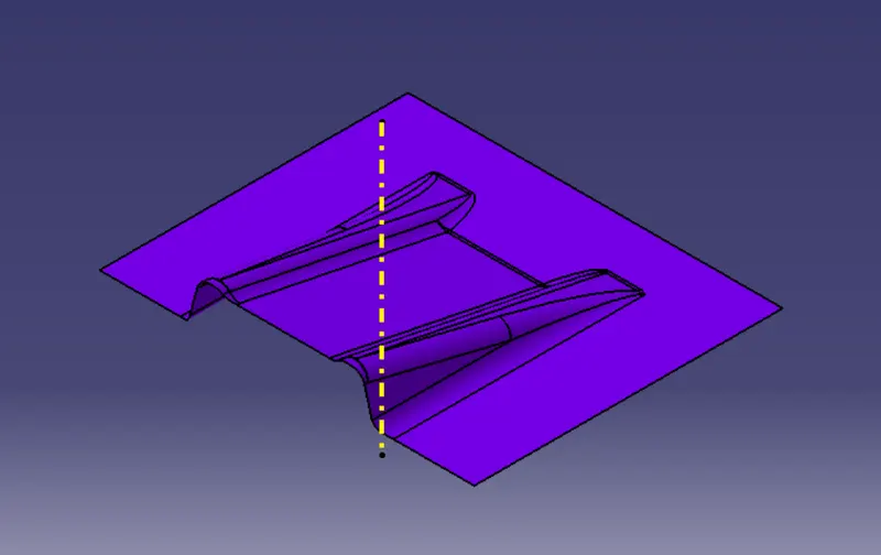
BASE BRACKET : CLASS B SURFACE
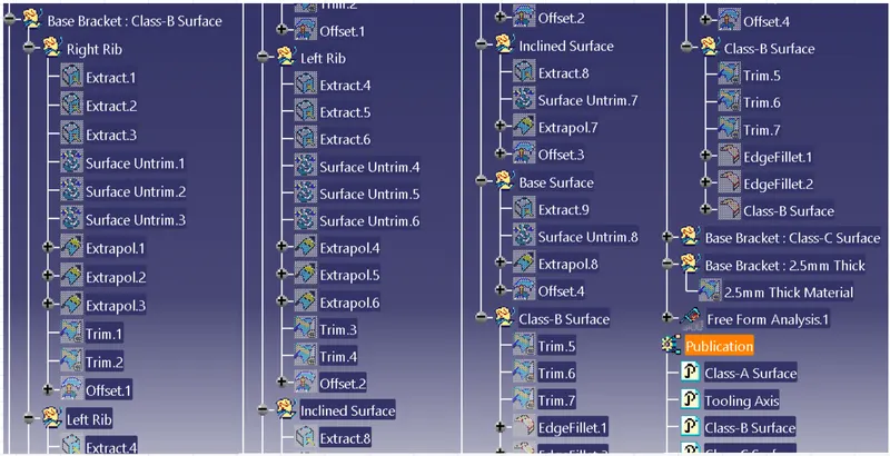
Class B Surface : Tree Structure
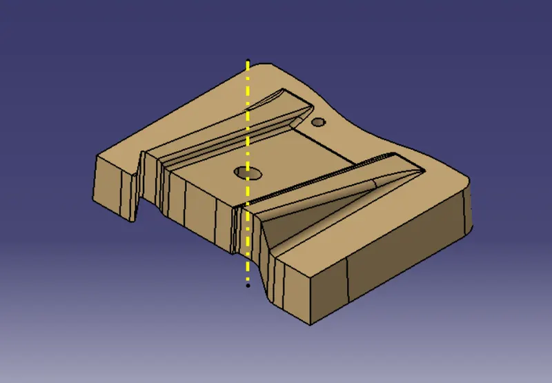
BASE BRACKET : CLASS C SURFACE
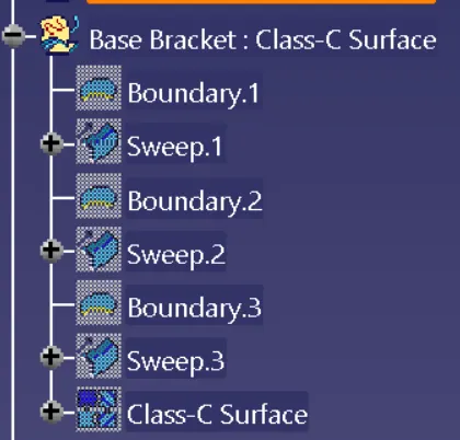
Class C Surface : Tree Structure
BASE BRACKET : FINAL COMPONENT
Front View
Side View
Top View