Week 9 - Attachment Feature Creation (Ribs & Screw Boss) - Challenge 1
Aim : To create the rib and Screw boss for the Drill Handle considering the design rules
Objective :
1.Create the rib for the Drill Handle considering the design rules
2.Create the Screw boss for the Drill Handle considering the design rules
Design rules :
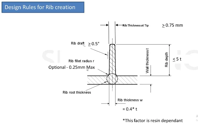
for rib design
for screw boss
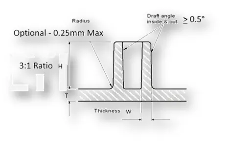
General Guidelines for Bosses:
Draft - 0.5 degrees on the walls of boss
Thickness - Typically 40%* of the nominal wall at the base.
Height to Diameter Ratio - 3:1
Radii - 0.25mm maximum radii.
Note : we consider thickness is 2.5 for component.
Details Report on Rib and Screw Boss cretions :
we get the part file for door handle in part file only class a surface placed so we can create the rib as well as screw boss so 1stly we create class b and c surface than we get close profile and solid body so 1st done all process step wise
Procedure Creation of model that class A B & C surfaces and rib and screw boss design :
Class A surface :
this placed our part files and we can only named it and color it
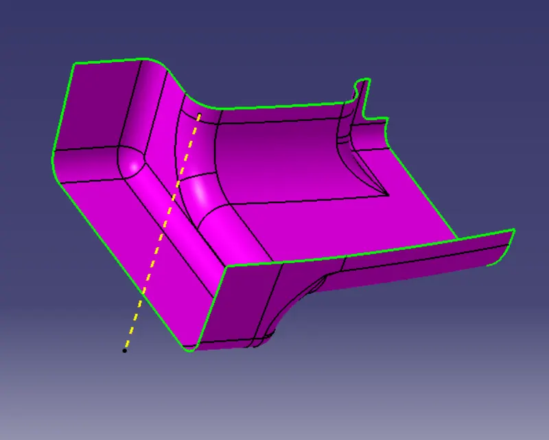
After that we create the tooling axis
Tooling axis :
we know that create the tooling axis 1st find plane surface of the component because tooling axis shows the direction of the moulding jet so we find it and extract the this surface than create point on it than we used the line command and choose the point and direaction option and select the point which erarist created and we proper direction and create line this line called as tooling axis shown in below figures
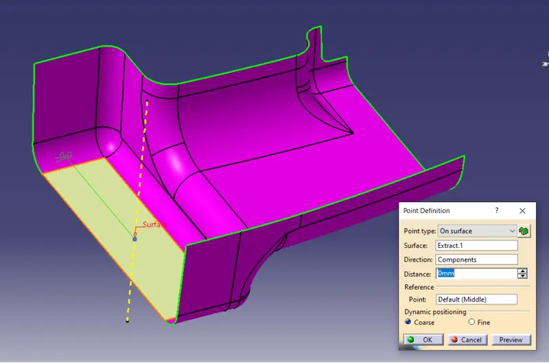
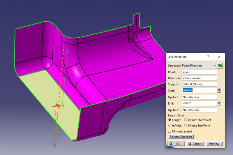
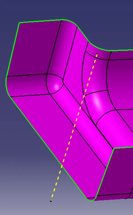
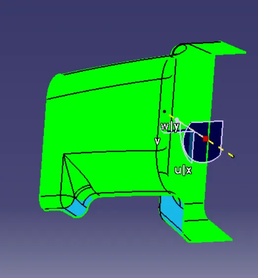
by cheking of tooling direction right or not so we used draft analysis option done draft analysis we get all part green which perpendicular to the tooling axis so your tooling axis is right way and see it below figure.
after that we create the b surface
B surface :
so creations of b surface so we offeset the class a surface for 2.5mm dimension because the we already mention in above so offset it in that some part not offset irreguraty on it so we slove it so goto the multi section surface and choose curve and guide option as per design requiredment and get final part i.e b surfaces
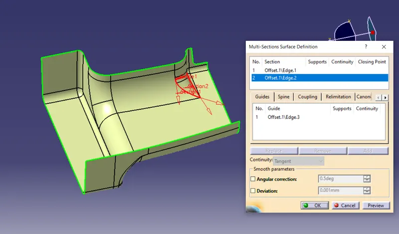
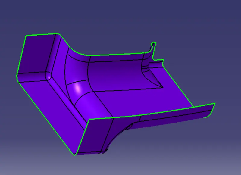
after that create the c surface
C surface :
we create the c surface by the used sweep command and get boundry of the class a as per requirdment and sweep the desired part as per design consideration this process done the repeate when all side sweep it than join it and get one surface this call as c surface
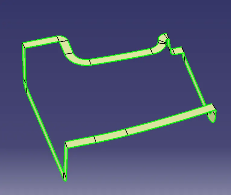
after that we get the close surface by using trim command so 1st we join the class a and c surface than trim thus join with b surface so we get desired output that is close surface
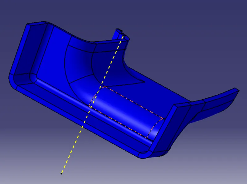
after that we get solid part so goto mechanical design in that part design and goto colse surface option and select this final output and click ok get solid surface
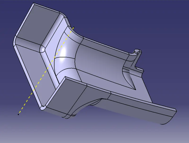
done all thinck now we goto design of rib and screw boss
Rib Design :
Rib
Rib provides an economical way to increase stiffness and strength to the mould parts without increasing the overall thickness of the wall. It is thin protrusion that extended perpendicular from the wall.
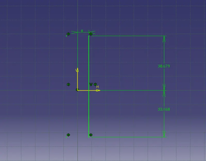
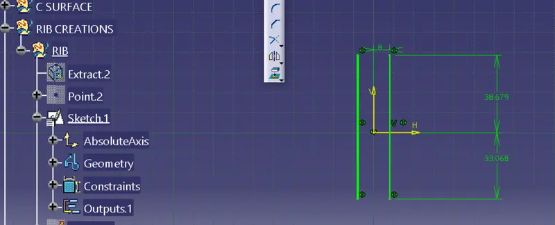
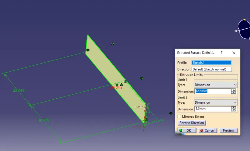
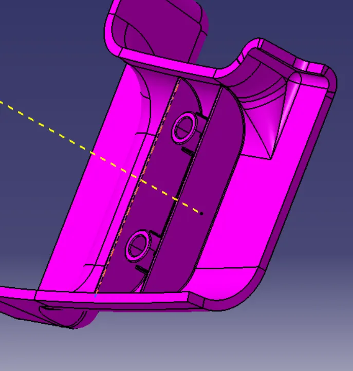
in rib design we create new geometric file and extract that surface where you create the rib so goto sketch and select that extract surface and create sketch so goto line and draw a line and get proper dimention and extrud it and get proper dimention as per rib design consideration which mention in above so we get height on rib is 12.5 and tickness is 1 mm after that we create new body and used thick command thick the extrude for 1mm as per design consideration than we taper it for 0.5 deagree both side as per design considertion than assemble it main body and used uniontrim option remove unwanted part and than fillet it as 0.25 mm dimention as per design rules same opertion done for second rib
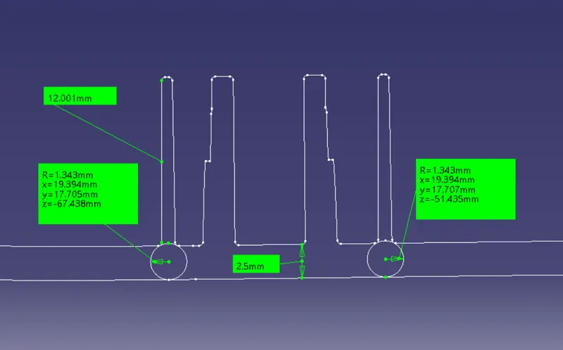
Rib root thickness analysis
To check the Rib root thickness, first take perpendicular intersection across the body and the Rib and then have to sketch a circle which tangent to the Rib base or root area by using tritangent type circle. The value must be within 30% greater of the wall thickness.
Screw Boss Design :
Screw Boss
Screw boss are used as a point for attachment and assembly, most common in as cylindrical projection with hole design to receive screw or other types of fastening hardware.
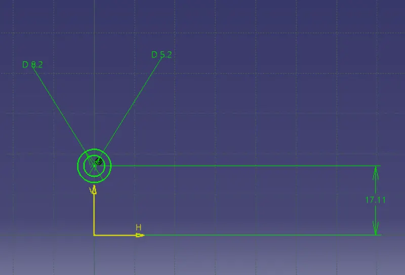
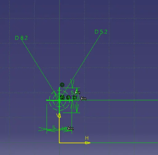
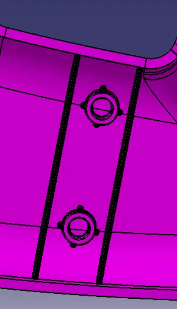
in screw boss design same create new geometric set and goto skecth and draw the two circle and get dimention that is diameter is 5.2 for inner as per design consideration which mention in above and outer is 8.2 than pad it before that select new body than taper it and assemble with solide body and than rib for support the screw boss and that rib is only prupose to support the boss again goto skech and draw two line which cross each other get proper dimention than pad it and thick it and thickness is 1 mm than we goto uniontrim and remove inside part or porion than taper it after that we create th fillet and get final screw boss and follow samr process for onther screw boss also
Final component :
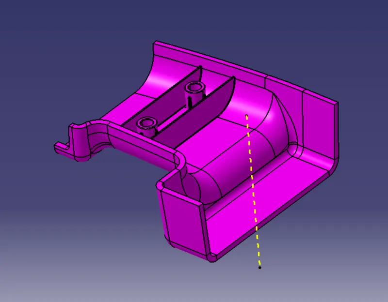
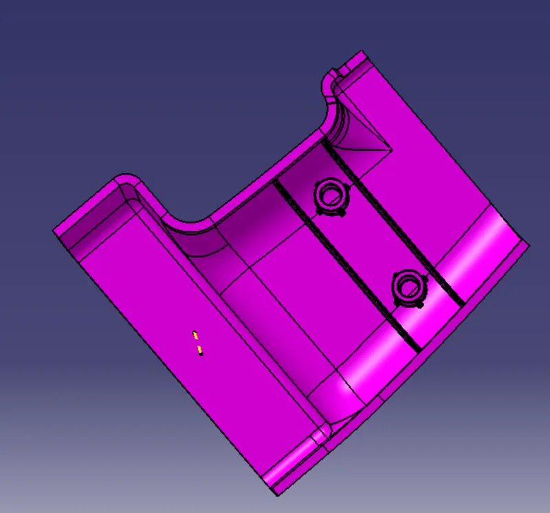
After that we goto the draft analysis for final component and parts
Draft Analysis :
Darft analysis is a tool perform to check the product easliy removed from the core and cavity.
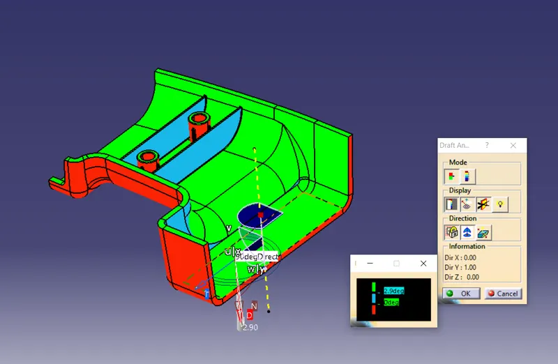
1st we goto draft analysis and in that 1stly fixed the compass and tooling axis properly than we goto the analysis parts and get the set of direction proper manner
in the draft analysis of door handle, most of surface are green that means the surface has draft angle more than 2.9 degree and some surface has draft angle in between 3 to 1 degree which is shown in sky color and there is not negative draft surface here.
some surface of left side of Class-C surface has negative draft upto -0.73 degree that is below 0 degree which show in red color.
Note : we attch the part file of this challange with attachment section pls see it .