Week 9 - Attachment Feature Creation (Ribs & Screw Boss) - Challenge 1
Report :-
At initial level, we understand, provide a class A Surface by applying the boundary Wether it’s closed or not
As the Class A surface boundary condition is satisfied. We proceed the same for the tooling axis creation
While working on tooling axis initially locate the point where the coordinate system can be mounted so that the intersection of the provided class A surface can be taken with the reference planes of the coordinate system
Tooling Axis
After locating the coordinate systems to an intersection of the class, a surface with the reference planes.
Onwards took an intersection between the provided class A and the reference planes
1. As the one of intersection observed perpendicular hence considered perpendicular tooling axis
2. for another plane draw line using two point method on both sides of intersection generated. onwards drawn a bisecting line for these two lines at origin of co-ordinate axis defined and considered it as Dummy Tooling Axis.
Onwards, with the help of draft analysis, tools lock the compass on the dummy tooling access and proceed for the trial. Draft analysis
The draft analysis reports found satisfactory with the assumed a dummy tooling axis and hence proceed further with considering the dummy tooling axis as tooling axis
Now, with the part design thickness tool converted provided class A to Part and proceed for Ribs and screw boss design
Now to defined tooling axis is super to find okay with the final plastic products designed
For the same process to the draft analysis of the final plastic product designed with the help of tooling axis and the draft analysis report found satisfactory
The green coloured services gives the positive draft man. Red coloured services shows the negative draft directions.
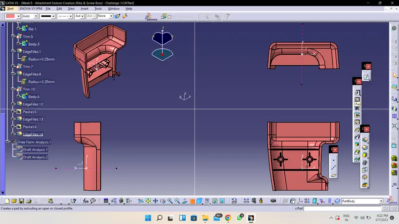
Screenshots of the completed design in various orientations (Isometric, Front, Side, and Top View)
- ATTACHMENT
Week 9 - Attachment Feature Creation (Ribs & Screw Boss) - Challenge 1