Week 9 - Attachment Feature Creation (Ribs & Screw Boss) - Challenge 1
Rib and Screw Boss creation
To create the rib and screw boss for the drill handle,and to perform the draft analysis on the final component.
Objective
1)Create the tooling axis
2)Design Class B,C surface.
3)Design solid surface.
4)Create Rib and Screw boss.
5)Perform draft analysis.
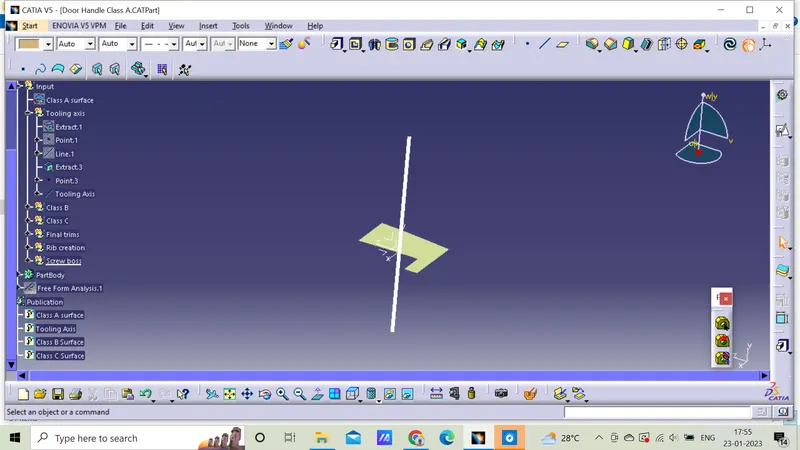
Tooling axis
1)Usually it is created by bisecting method.
2)The tooling direction for the given Class A surface is along Y-axis direction.
3)Flat surface on the center part is extracted for creating the tooling axis in y direction.
4)Created a midpoint along the direction Y-axis and formed tooling direction.
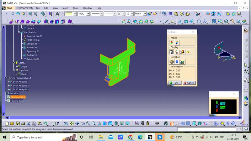
Draft analysis on Class A Surface
Designers of plastic parts and mould tooling manufacturers can use the Draft Analysis tool to check the correct application of draft to the faces of their part. With draft analysis, you can verify draft angles, examine angle changes within a face, as well as locate parting lines, injection, and ejection surfaces in parts.
1)Color codes are classified and Draft angle is applied.
2)Running point analysis is used to display permissible draft and angles.
3)Here,Green denotes more than 3degrees and blue denotes less than 3 degrees.
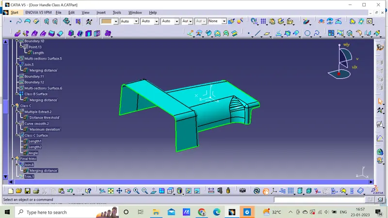
Class B Surface
1)It is the surface which contains engineering aspects of a model,it also minimal imperfections.
2)It is normally specified on surfaces such as external covers, panels, and parts that are fairly prominent.
3)The Class-B surface is a surface below a certain thickness from the class-A surface.
4)After the analysis is done then the provided surface is extracted and then they are off-setted to the thickness value which is 2.5mm below the A-class surface after that the extracted surfaces are done by using the Multi-sections surface,boundary,multiple extract etc..,
Below are the images
Class C Surface
1)Class C is often specified for interior surfaces not readily visible, surfaces that will be covered by another part when assembled the Class C finish allows more imperfections than Class A or B.
2)It is the class-A surface, we can create the class-A boundary curve and sweep in a single stretch.
3)Created a sweep of 90 degree with reference to the surface option.
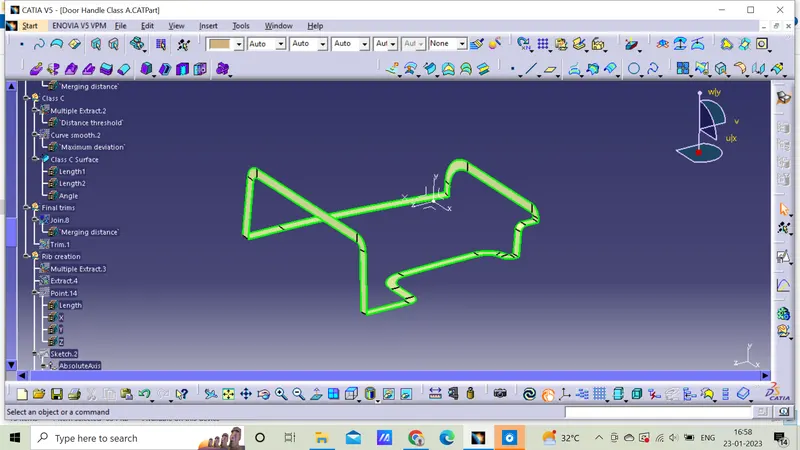
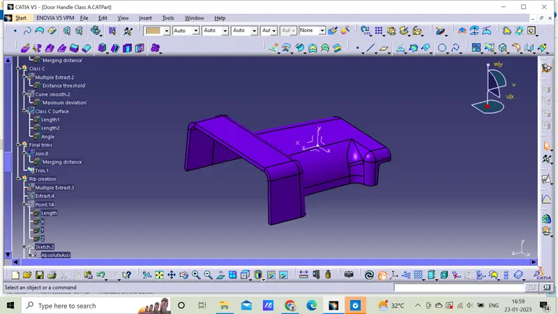
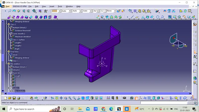
Final surface after trimming
Joining Class A,C Surfaces and trimming with Class B Surface.
Creation of Ribs
The analysis for the dimension is one of the very important analyses to avoid problems in the injection molding process for the component dimensions. the problems like sink marks, flow lines,weld lines, and warping.
Ribs are indispensable functional structures on many plastic parts. It can effectively improve the rigidity and strength of plastic parts like the H beam.
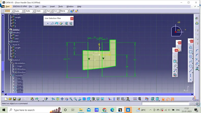
1)First, the base surface where the rib has to be created is extracted using the Extract command. A positioned sketch is created and the profile for the rib is drawn.
2)Next, the profile is extruded, to find the height,h=Wall thickness * 5.(2.5*5=12.5mm height)
3)Extruded surface is thickened,
Thickness,w=0.4*t.(0.4*2.5=1mm)
1mm is the thickness of rib.
sketches for rib design,
Below are the images,
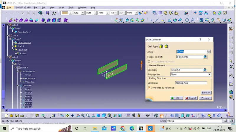
Edge fillet,
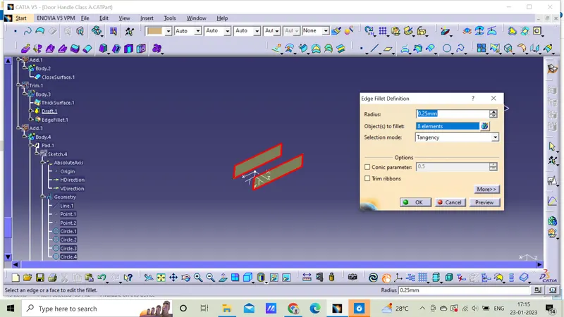
Rib creation,
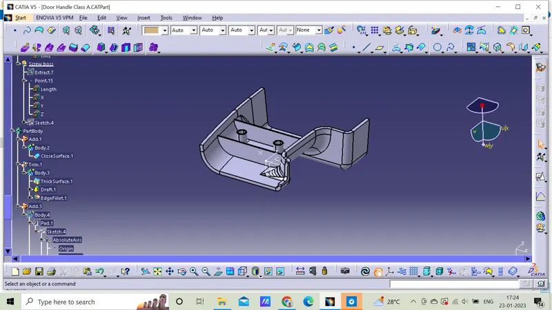
Screw boss
Bosses are common structures on plastic parts in home appliances and interior and exterior of auto-mobiles, mainly for positioning and fastening.
The base of bosses often cause sink marks on the back surface of a part, this is because of the large wall thickness.
1)Initially the sketch is created with diameter of (m6 bolt) 5.2mm.
2)Thickness -Typically 40%* of the nominal wall at the base in one side,
40% of 2.5 =1 mm,one side =7.2mm.
3)Finally it is paded to height of 12mm (height to diameter ratio 3:1).
Sketch of the screw boss,
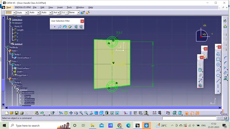
Below are the images,
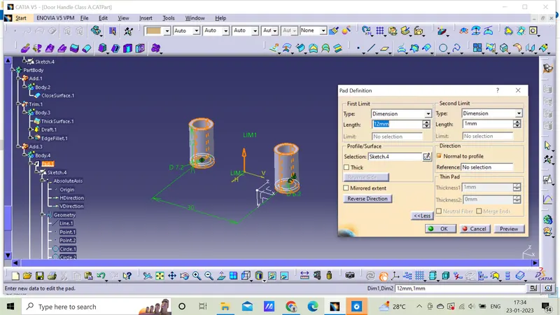
It is drafted and filleted to the required dimensions.
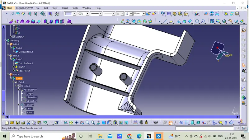
Draft analysis on Solid product,
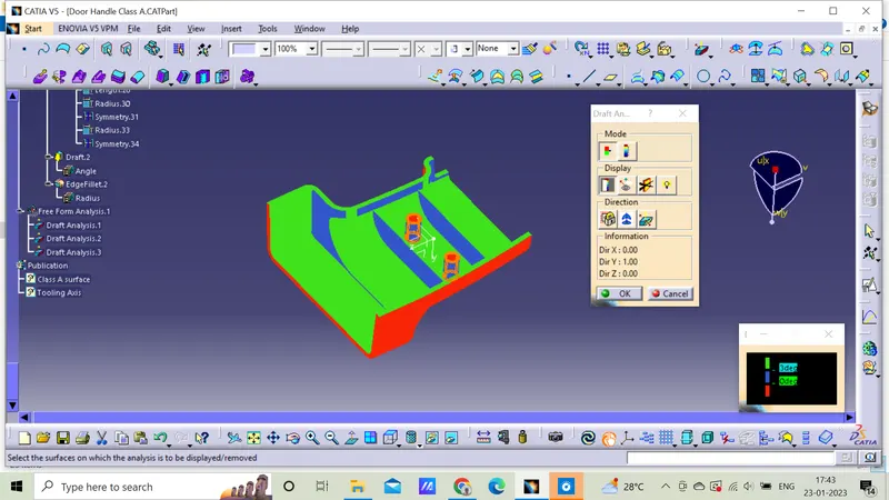
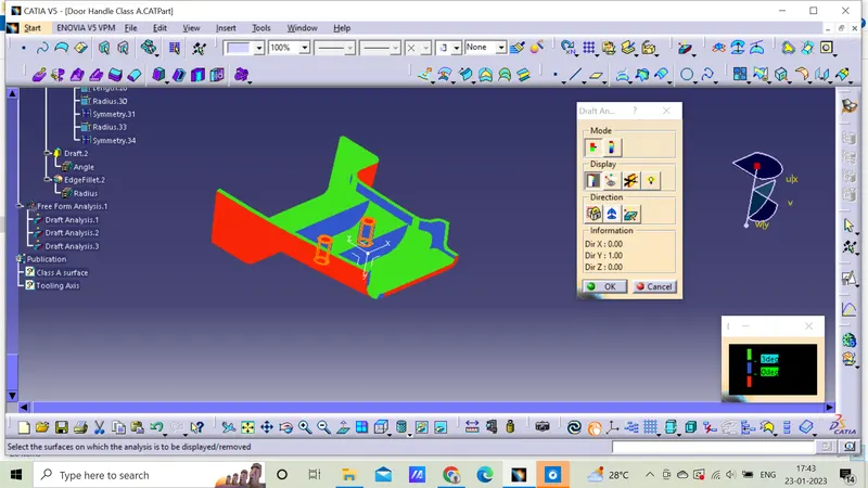
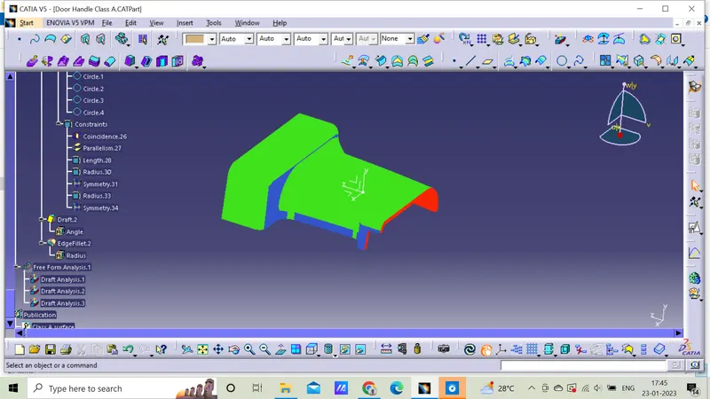
1)Draft analysis is done using featured draft analysis tool.
2)Use the compass fucnction to aling the compass to the tooling direction and lock the direction using lock function in the draft analysis tool bar.
3)The surface is showing green colour so that the surface clears the minimum draft angle of 3 degree.
4)By using the analysis under the running point we can check draft angle on the individual faces. It shows how much draft on specific points when we move towards another point.
Conclusion,
The attachment feature (Ribs and Screw boss) is done.