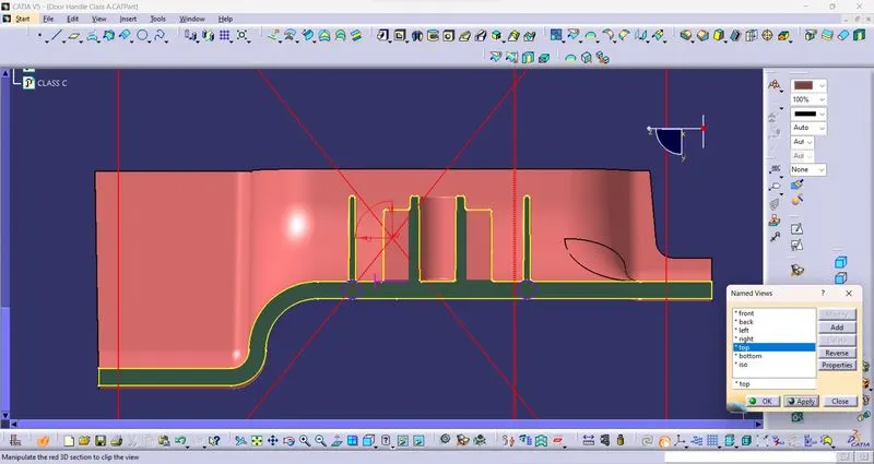
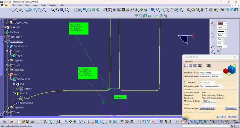
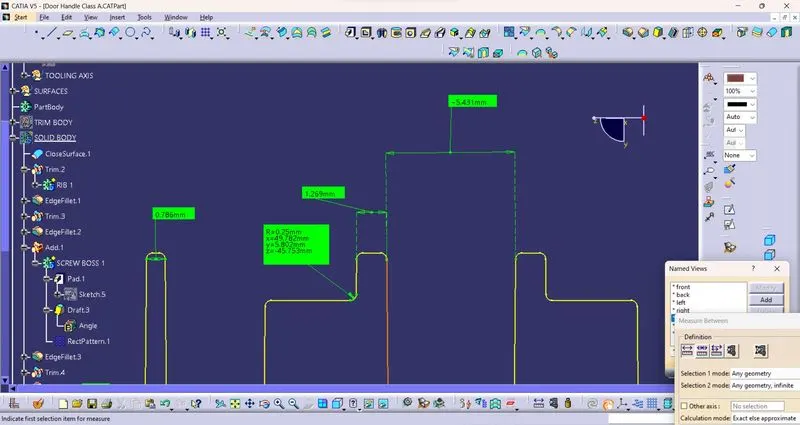
Week 9 - Attachment Feature Creation (Ribs & Screw Boss) - Challenge 1
DOOR HANDLE DESIGN
Objective:
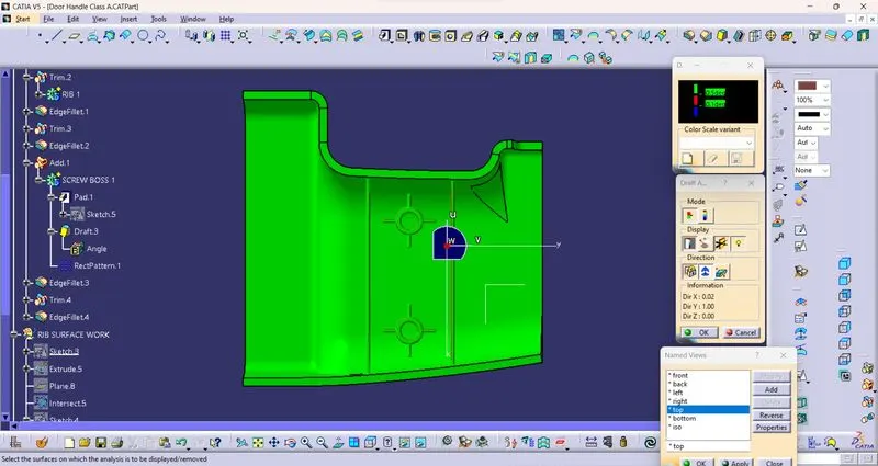
Creating the tooling axis,Ribs & Screw bosses for the given door handle model meeting the requirements of the draft angle and perform the Draft analysis on the model.
- Checking continuity of given class A surface:
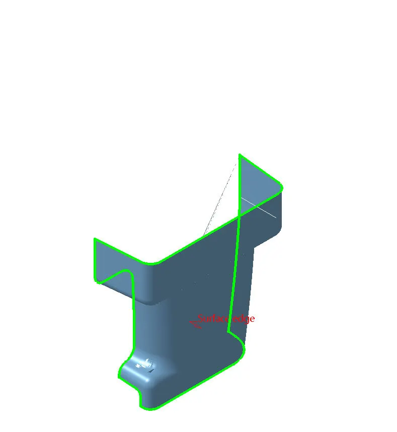
First of all we have to check continuity of given class A surface to ensure class A surface is properly joined or no discontinuity present. This can be done using join or boundary command in CATIA . By looking visually in below image we see that surface has continuous connected boundry as highlighted by green line.
- Tooling axis direction:
Next step is to decide tooling axis direction. Tooling axis is a direction in which mould or core & cavity opens. Analyzing model visually to see which direction is most suitable for tooling axis. as shown in below image.
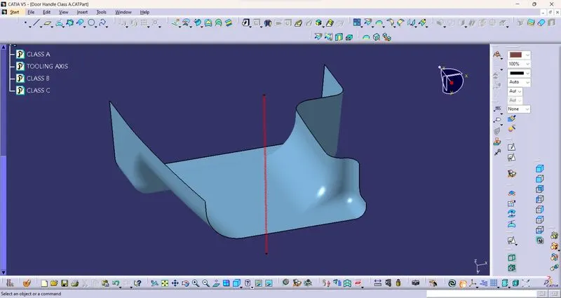
- Initial steps has to be taken :
Specify tooling axis location
we will use bisecting method to find real tooling axis.
Insert a plane. Take intersection of XY plane with class A surface. We will get the two curve
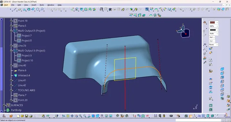
Now we have to see which surface will create problem or will be difficult for tooling. Because the surface which 90° to tolling axis will be cleared. So we have to check surface which lie parallel to tooling axis direction. Make line along parallel surface using point to point direction. Here we get two lines, now we will bisect the two lines & choose vertical direction.
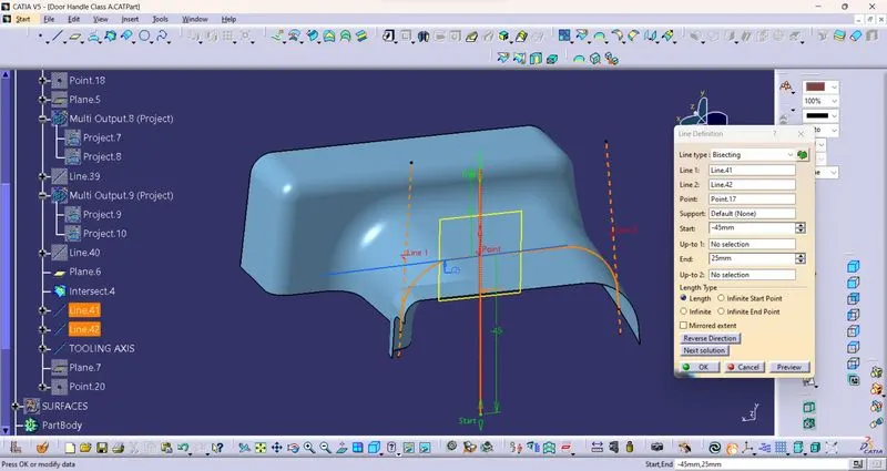
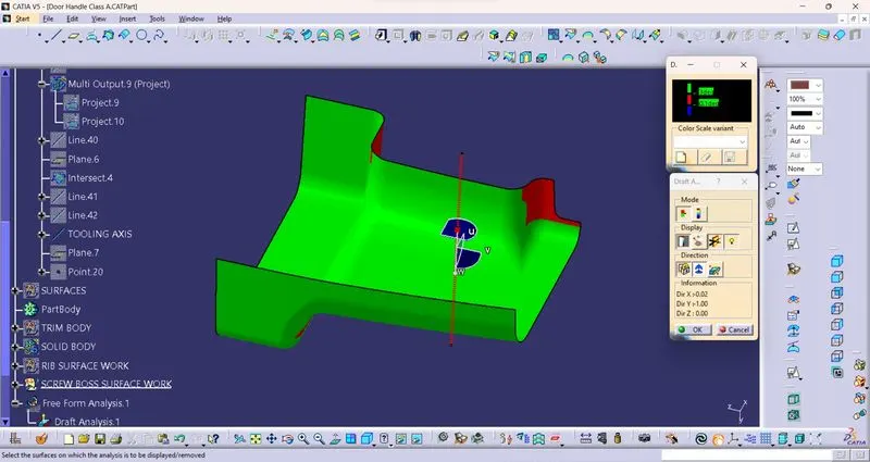
- DRAFT ANALYSIS OF CLASS A SURFACE:
B SURFACE:
- In the case of Class A the surface below is called core and the surface above is called cavity.
- Class A is an aesthetics surface and class B is an engineering surface.
- B surface should be inside the class A surface.
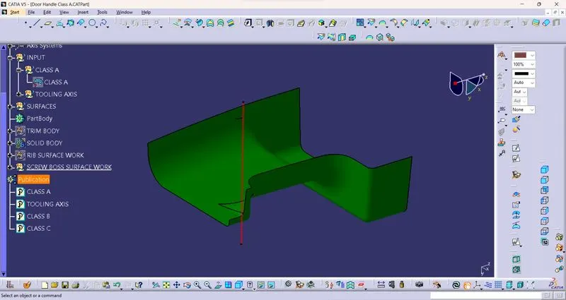
- B surface can be divided into four surfaces the side walls, top walls, outer flange and the base surface and later trim them altogether.
- First step is to create the side wall surfaces by extracting the required surface from Class A and untrimmed it thus we will get a single surface which will be extrapolated to get the required size and finally offset it to the inner side of class A as per the thickness of the material and trim them together and apply the required fillet by measuring the values from class A.
- Base surface of the component is then extract, untrimmed, extrapolated, offset and trimmed.
- The top walls can be directly extrapolated from the extracted surfaces and offset it for the required size of the material.
- Then join the base, side wall and top wall by trim operations.
- As the Outer flange is surface complex it can be divided into two parts and extract them then go for extrapolation, offset, split and join operations and finally check the for the connectivity by intersecting method.
- Now all the four geometries are trimmed together to get the B surface.
- Fillet is applied to the required surfaces by measuring the fillet value from the class A surface.
GREEN COLOUR SHOWING CLASS-B SURFACE:
C SURFACE:
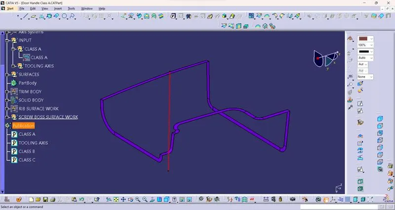
- C surface has been created from the boundary lines of class A surface and by extracting the supporting surfaces then sweep the boundary lines with reference to the extracted surfaces.
- In order to get the C surface first we have to create a boundary lines of class A surface or by using multiple extrapolated command and check for the continuity of it.
- Create a sweep with reference to the curve and the reference surface with a 90 degree angle and give the inside direction Check for the continuity of the surfaces if there is any gap go for extrapolated and trim all together now we will get the class C surface.
Then join the class A surface and C surfaces together by join command then check it for connectivity of the surfaces if it is ok then finally trimmed it with B surface we will get the final component again check whether the final body is closed by using boundary command.
Closed solid body is created by using the close surface on part workbench by selecting the final Trimmed component and do the draft analysis for the same.
BLUE COLOUR SHOWING CLASS-C SURFACE:
CLASS B SURFACE FEATURES:
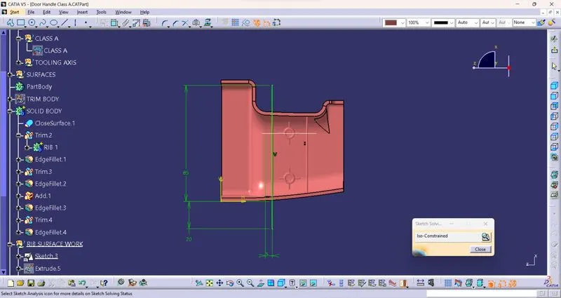
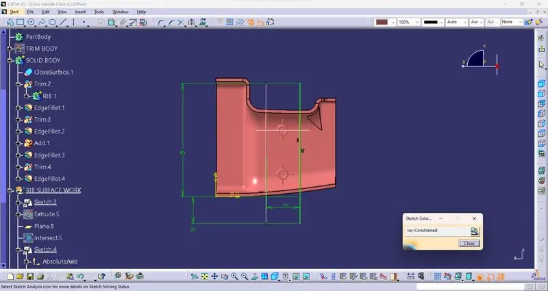
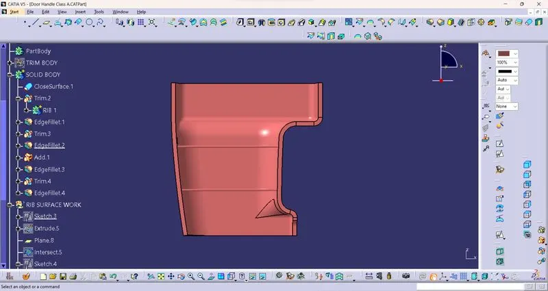
- RIBS CREATION:
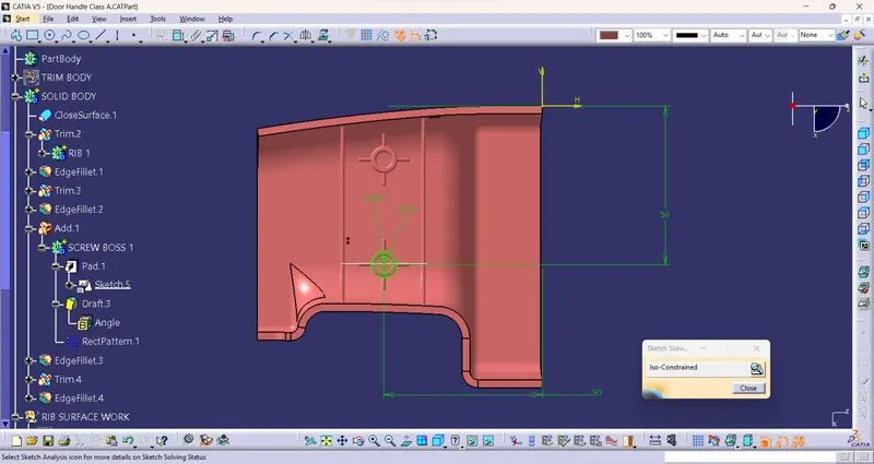
- SCREW BOSSES CREATION:
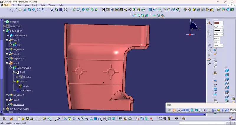
DRAFT ANALYSIS ON SOLID BODY:
3D PART VIEWS:
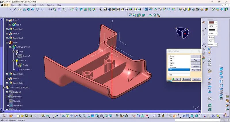
ISOMETRIC VIEW
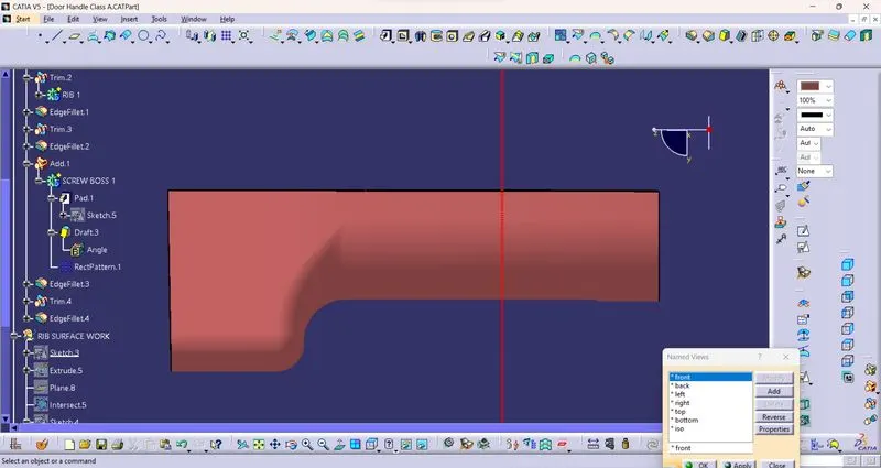
FRONT VIEW
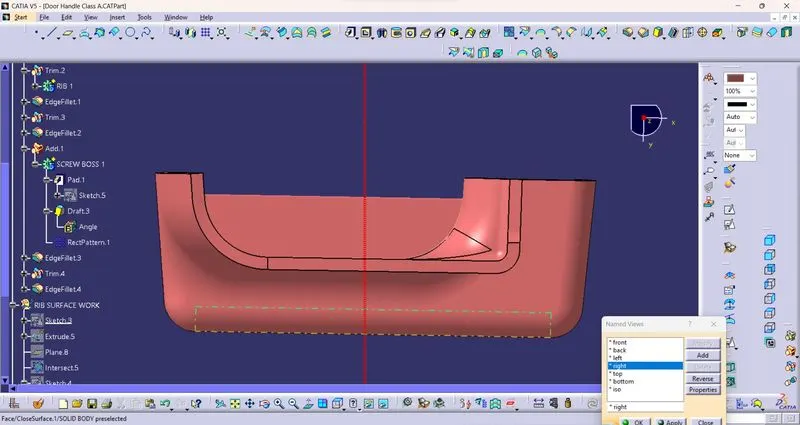
SIDE VIEW
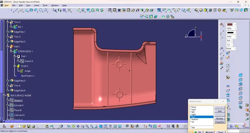
TOP VIEW
INTERSECTION: