Week 9 - Attachment Feature Creation (Ribs & Screw Boss) - Challenge 1
REPORT WRITING
CONTENTS
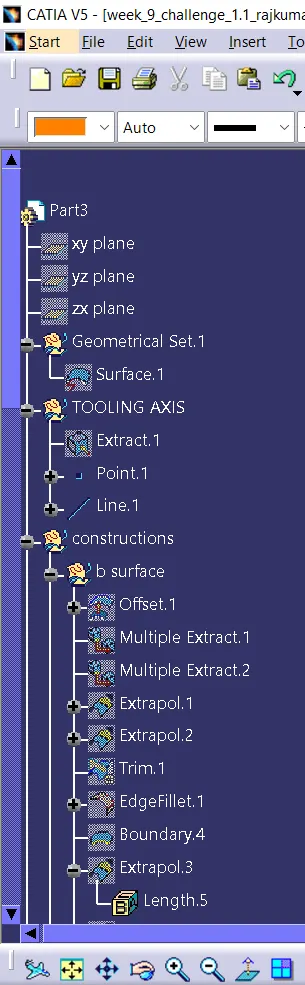
- TOOLING AXIS
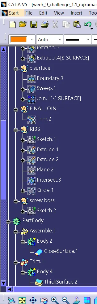
- CREATION OF B AND C SURFACE
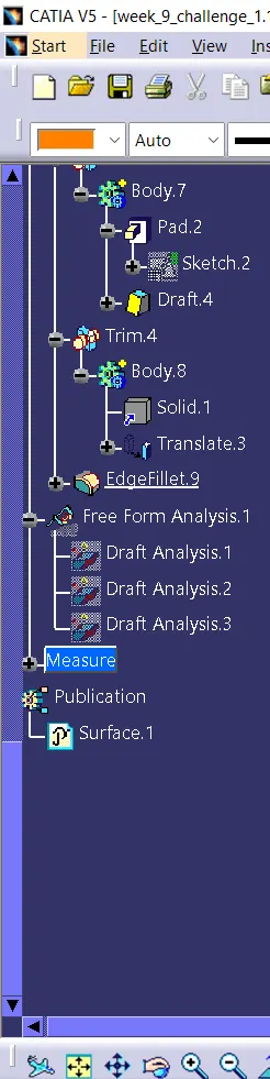
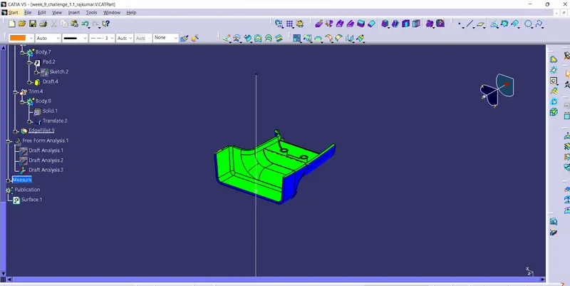
- DRAFT ANALYSIS
- RIBS CREATION
- SCREWBOSS CREATION
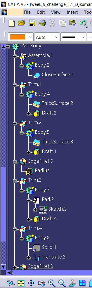
- FINAL DRAFT
TOOLING AXIS
The Tooling Course is essentially the course that the form pulls a portion. The shape is built in two isolated pieces, essentially. You've got a Depth side and you've got the Center side. The Center pulls separated from the Depth and that's the Color line or the Tooling Direction.By dissecting the component the foremost effortlessly ejectable heading is some place near to the Z direction,(might be inclined to it) so we have made a portray on the YZ plane of Hub Framework) to make a bisecting line considering the 2 faces which may well be troublesome to be tooled.
CREATION OF B AND C SURFACE
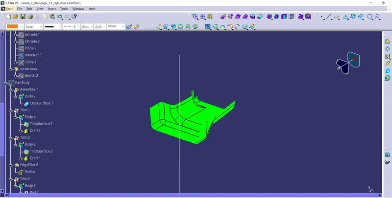
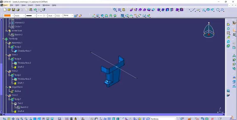
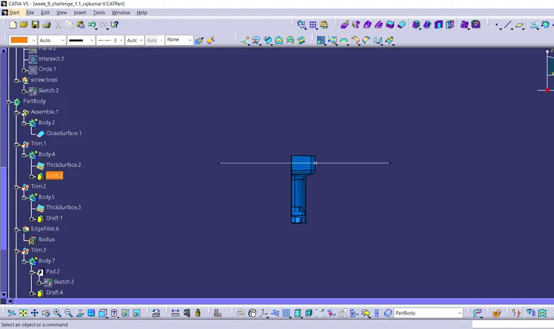
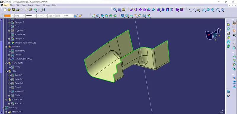
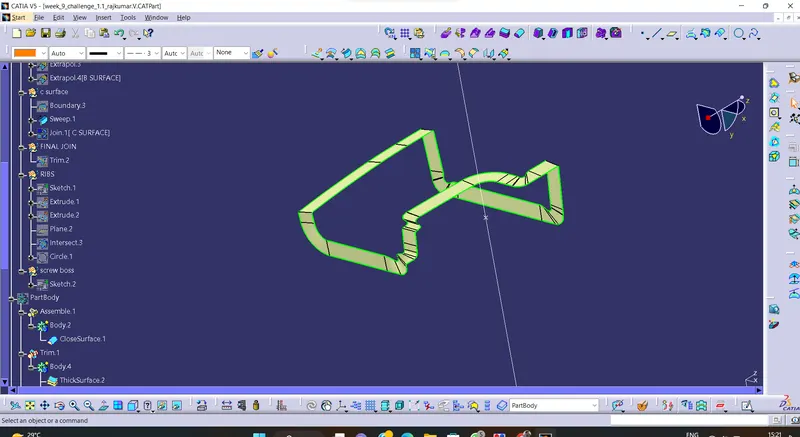
Extricate the surfaces from the course A utilizing different extricate and untrim them. Use Extrapolate to create beyond any doubt that all the untrims are legitimately met to trim and counterbalanced the surfaces to 2.5 mm to make the thickness. Trim the additional surfaces utilizing trim command. Insert them into modern geometrical set and title it with respective portion names. Apply filets to the show after making the complete surface. If the edges are exterior the filet esteem will be included to the thickness of the component and on the off chance that the edges are interior, the filet esteem will be subtracted from the thickness of the component, for occasion the thickness of the component Is 2.5mm the filet esteem is 15mm so the exterior parcel esteem ought to be 17.5mm and internal eges should be filleted 12.5mm to urge uniform thickness. Perform trims one at a time so that it'll be clear to get it.Extricate the boundary from the course A surface utilizing boundary command. Using dismantle device to isolate the boundary as the boundary contains domains. Use clear command > select profile sort line > subtype as with draft heading > select direct bend and draft heading > draft point as 3 degree > see.
RIBS CREATION
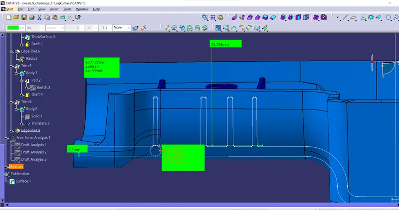
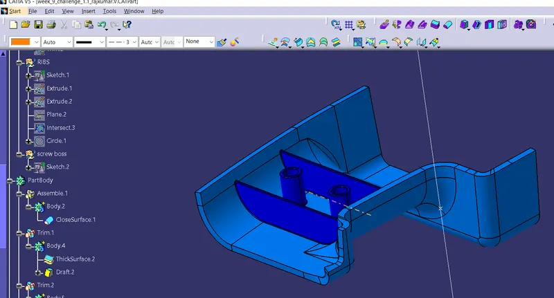
Ribs are lean divider bulges that amplify oppositely from a divider or plane. They are ordinarily found in clusters advertising bolster to a plane that would have something else been as well thick, but can moreover be stand-alone bolster for a single divider. They are commonly utilized to supply extra back and quality to a portion. Thickness and area are basic to rib design. First, the base surface where the rib has got to be made is extricated utilizing the Extricate command. A situated outline is made and the profile for the rib is drawn.
SCREW BOSS CREATION
FINAL DRAFT
CONCLUSION
- The Tooling axis and the part with B Side Features is created from the given Class A Surface and Draft Analysis is Performed.