Radar Mast & Final Assembly of Yacht
DESIGNING OF THE YATCH MODEL
OBJECTIVE
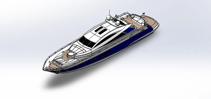
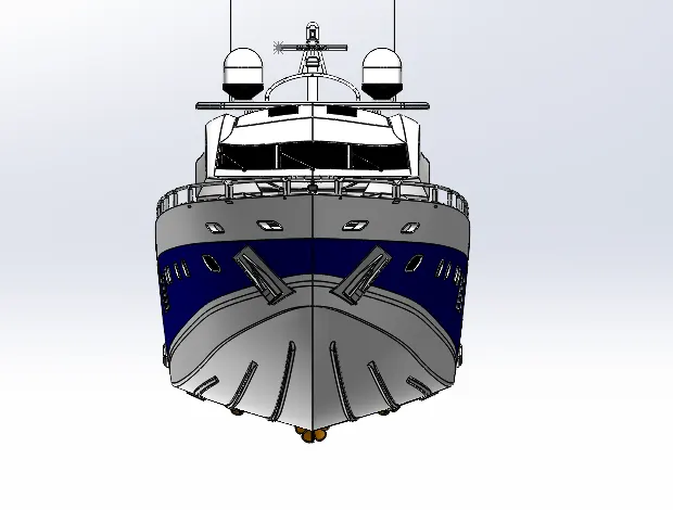
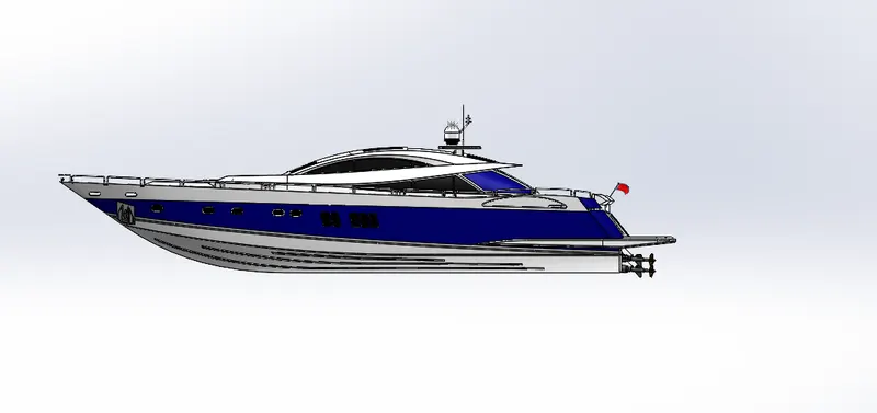
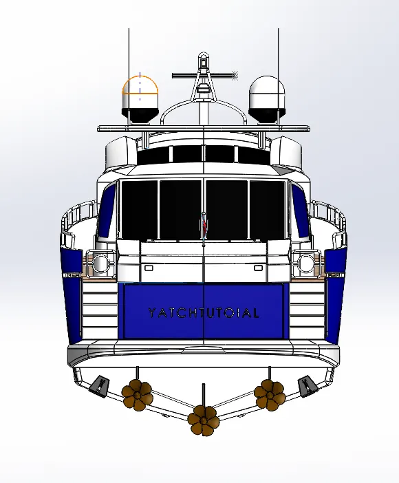
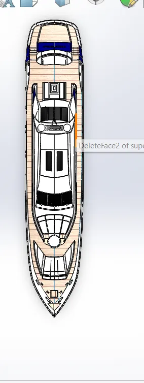
The objective of the extend is to plan and demonstrate all the parts of a predator yacht and amassing it to make the photo-realistic rendering of the yacht.
INTRODUCTION
In this extend the Predator Yacht was taken as a conceptual show, to get it the 3D demonstrating strategy of Solid modelling and Surface demonstrating. Each and each portion of the yacht was planned and displayed utilizing SOLIDWORKS. At that point the demonstrated parts were collected by legitimate mates and limitations to form the Photo-Realistic rendered picture of the Yacht
DESIGN METHODOLOGY
MODELLING
1.HULL
2.SUPERSTRUCTURE
3.PROPELLAR
4.GARAGE DOOR
5.RADAR
6.RADARMAST
7.MIDDLE SEAT
8.FRONT SEAT
9.REAR SEAT
ASSEMBLING
1.MATING
2.EXPLODED VIEW
RENDERING
1.DECALS
2.CAMERAS
3.LIGHTS
4.SCENES
5.ENVIRONMENT
6.APPERANCES
MODELLING THE HULL
COMMANDS USED
Line
Spline
Circle
Rectangle
Arc
Slot
3-D Sketch
Sketch picture
Extruded Surface
Revolved Surface
Lofted Surface
Surface Trim
Surface Fill
Surface Knit
Delete Face
Project Curve
Chamfer
Fillets
Reference Plane
Split
Split Line
Extruded Boss
Extruded Cut
Mirror
MODELLING PROCEDURE
The primary step for modelling the Yacht was making a blueprint of it. Then the blueprint was set at the desired planes, by utilizing it to begin with the body was designed. To get the shape of the hull the anticipated bend was produced by drawing the desired portray utilizing splines with the assistance of blueprint. Then the bends were lobbed to make a lobbed surface and the remaining undesirable surface was trimmed utilizing surface trim. Then the back parcel of the body where the propeller ought to be put was expelled utilizing Expelled Surface and all the surfaces made must be Knitted together to expel the holes between the surfaces. Then the counterbalanced alternative was utilized, and another surface was made, and each surface was filled utilizing surface fill to form the external shell of the frame which can be changed over into a solid body at final.
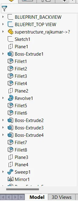
Shell include was utilized to make the front parcel of the frame where the deck surface meets. Then the deck surface was made utilizing Extruded Boss/Base and Expelled Cut. Then the specified chamfers and filets were made wherever necessary. All the windows and Openings were made utilizing Expelled Cut and Filets were include around the edges. For making the smooth edges around the compartment window the reference plane were created and a circle for required measurements were make punctured and after that cleared around the edge of the windows. The Rails at the foot of the yacht were made utilizing Expelled Boss/Base and the chamfers were connected both the sides. The Cable Rollers were made utilizing Expelled Boss/Base and Cleared Boss/Base and the head portion of it was made utilizing Spun Boss/Base and Expelled Cut was utilized to cut through the expel and a Arch was made over it. Helix/Spiral portray was made to clear the rope around the Cable Rollers.
By utilizing Opening choice, the Rope holders were expelled and the arch was connected and after that the Linear Design was utilized to form one more. The window bars were made utilizing Expelled Boss/Base. The staircase was made by utilizing expelled boss/base and the hand back bar was made using Swept Boss/Base. The Railings around the Frame was created with the assistance of diagram and the anticipated bend was created and the railing reference was cleared utilizing Cleared Boss/Base. The Axles for the propeller and the surfer were made using Revolved Boss/Base alternative and utilizing the 3d sketch. The Grapples were made by portraying the primary half and expelled utilizing Expelled Boss/Base and the other half was mirrored. Finally, the Carport Parcel was made by utilizing Expelled Cut and the parcel was spared for afterward utilize by utilizing Part option. By utilizing the Part line alternative, the Portray parcel for our frame was part separately. Then the other half of the Frame and the Hub of the surfer and propeller was reflected.
MODELLING OF THE SUPERSTRUCTURE
COMMANDS USED
Sketch Picture
3D Sketch
Line
Spline
Circle
Rectangle
Centre Point Arc
Extruded Surface
Swept Surface
Ruled Surface
Knit Surface
Trim Surface
Extend Surface
Filled Surface
Lofted Surface
Revolved Surface
Fillet
Chamfer
Project Curve
Reference Curve
Convert Entities
Split
Split Line
MODELLING PROCEDURE
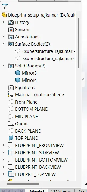
The deck surface from the frame was imported and the superstructure was demonstrated over it. The side surface of the Superstructure was made by utilizing Expelled Surface, Lobbed Surface, Filled Surface, Trim Surface, and Sew Surface. The Front side of the Superstructure was planned to have four rest beds which were made utilizing Expelled Boss/Base, Filets and Dome. The front edge of the superstructure was given with a Water Highlight which was made utilizing Expelled Boss/Base, Expelled Cut, and filled with a water appearance. The Windshield was made by Expelled Cut and the wipers were made by utilizing 3D outline and reference plane with the assistance of Cleared Boss/Base. The Openings for the Superstructure were made by utilizing Expelled Surface, Trim Surface, and Amplify Surface.
Ruled Surface was utilized to fill the cleared-out edges. The Back Entryways of the Superstructure was made utilizing Expelled Cut, Filets and Reference Plane. Then all the surfaces created were Sewn together to create a strong body. The Superstructure comprise of two surface bodies and five strong bodies. One of the surfaces was the Deck Surface the other one was utilized to put the Radar Pole, so it was renamed as Radar Pole reference Surface. Then the other half was reflected, and the correct filets and appearance was included and at long last the portion was spared.
MODELLING OF THE PROPELLER
COMMANDS USED
Spline
Circle
Line
Revolved Boss/Base
Lofted Boss/Base
Extruded Cut
Reference Plane
Circular Pattern
Fillet
MODELLING PROCEDURE
The centre parcel of the Propeller was outlined and rotated utilizing Rotated Boss/Base. Then the Edges were made utilizing the Reference Plane, Lobbed Boss/Base and Fillet. Then the remaining five edges were made by utilizing Circular Pattern. Then the centre circular parcel was evacuated utilizing Expelled Cut option. Finally, the portion was spared by including the right appearance.
MODELLING OF GARAGE DOOR
COMMANDS USED
Line
Spline
Circle
Text
Extruded Cut
Reference Plane
Fillet
Shell
Mirror
MODELLING OF GARAGE DOOR PROCEDURE
The strong body part whereas making the Body was imported to demonstrate the Carport Door. By utilizing the Expelled Cut the Chamfered confront for the entryway was created. Then by utilizing the shell include the strong body for our carport entryway was made and appropriate filets were applied. Then the entryway holders on both sides were made utilizing Expelled Cut. Then the moment half of the Carport Entryway was made utilizing Reflect instrument after applying the desired fillets. Then the content over the carport entryway “YATCH TUTORIAL” was made utilizing the content alternative in outline feature. Finally, the portion was spared by applying appropriate appearance.
MODELLING OF RADAR
COMMANDS USED
Line
Text
Circle
Point
Extruded Boss/Base
Extruded Cut
Sketch Pattern
Fillet
Mirror
Split Line
MODELLING OF RADAR PROCEDURE
By drawing the specified portray the body of the Radar was made utilizing Expelled Boss/Base. By utilizing the Portray Design the four Dabbed gaps were made utilizing Expelled Boss/Base and Expelled Cut. The Radar includes a circular opening underneath which was made utilizing the Expelled Cut. The other half was reflected with the assistance of reflect tool. The Content over the Radar was made utilizing the Content choice in outline and after that the Part Line was used to produce over the confront of the radar. At final, the radar must be filleted around the edges of the body conjointly around the four holes. Finally, the portion was spared by including legitimate appearance.
MODELLING OF RADARMAST
COMMANDS USED
Sketch Picture
Line
Spline
Rectangle
Arcs
Extruded Boss/Base
Lofted Boss/Base
Revolved Boss/Base
Swept Boss/Base
Reference Plane
Projected Curve
Fillet
Mirror
Dome
Shell
MODELLING OF RADARMAST PROCEDURE
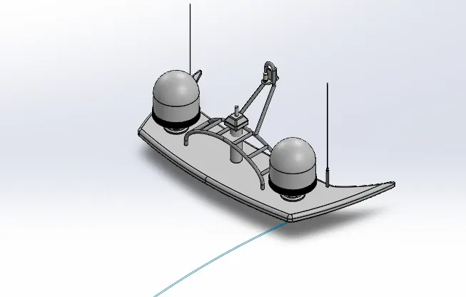
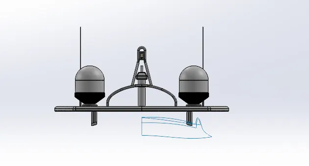
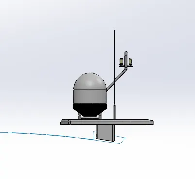
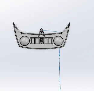
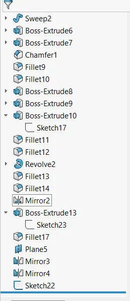
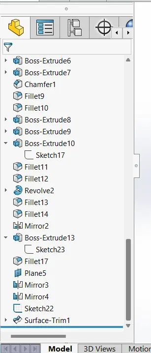
The primary half of the Radar was Displayed with the assistance of diagram and after that the other half was reflected with the assistance of Reflect tool. The body of the Radar was made utilizing Expelled Boss/Base and Spun Boss/Base. The radio wire for the radar was moreover made utilizing the Expelled Boss/Base. The light stand alongside the interfacing bar were made utilizing the Cleared Boss/Base and Reflect tool. The light was made by utilizing the anticipated bend and after that the bend was cleared utilizing cleared boss/base. The horns were made utilizing the Rotated Boss/Base, Arch and Shell. Then the filets and chamfers were connected wherever necessary. Finally, the portion was spared by applying fitting appearances.
MODELLING OF FRONT SEAT
COMMANDS USED
Sketch Picture
Line
Spline
Circle
Arcs
Extruded Surface
Lofted Surface
Trim Surface
Filled Surface
Knit Surface
Swept Surface
Revolved Surface
Extruded Cut
Revolved Boss/Base
Chamfer
Fillet
Mirror
Dome
MODELLING OF FRONT SEAT PROCEDURE
The Front situate of the Yacht was moreover made with the assistance of Blueprint. The to begin with half was displayed and the other half was reflected utilizing Reflect tool. The front situate was set some time recently the Superstructure confronting the Water Highlight of the Superstructure and the back conclusion must be put on the bow of the Yacht. The body of the Front Situate was demonstrated utilizing Cleared Surface, Expelled Surface, Filled Surface, lobbed surface and the undesirable portion was expelled utilizing Trim Surface. Then the four Rest Beds were made utilizing Expelled Boss/Base and the arch was made over the confront of the beds separately. Then the desired filets and chamfers were made with expelled lean surfaces. Finally, the portion was spared by including appropriate appearances.
MODELLING OF REAR SEAT
COMMANDS USED
Sketch Picture
Line
Spline
Circle
Arcs
Rectangle
Swept Surface
Extruded Surface
Off-set Surface
Filled Surface
Knit Surface
Ruled Surface
Lofted Surface
Reference Plane
Extruded Boss/Base
Revolved Boss/Base
Fillet
Mirror
MODELLING OF REAR SEAT PROCEDURE
The most body of the Raise Situate was displayed utilizing Cleared Surface, Off-set Surface and the remaining parcel was trimmed utilizing Trim Surface tool. By utilizing the Reference Plane, the Seats were made with the assistance of Hurled Surface, Surface Trim and Expanded Surface. The Hail Post was made utilizing Spun Boss/Base and the Hail was created by drawing the desired 3D portray and after that the 3D outlines were hurled to make the Flag. The Taillights were made by utilizing Expelled Boss/Base, Filets and Reflect tool. The Steel Doors For Stairs was outlined by utilizing the reference plane and the Cleared Surface. To evacuate the holes the all the Surfaces must be Weaved together utilizing Weave Surface. The required filets and chamfer were made some time recently reflecting the moment half utilizing Reflect apparatus and after reflecting the uncreated zones were filleted again. Finally, the portion was spared by including fitting appearances.
MODELLING OF MIDDLE SEAT
COMMANDS USED
Sketch Picture
Line
RECTANGLE
Extruded Boss/Base
Chamfer
Fillet
Mirror
Reference Plane
MODELLING OF MIDDLE SEAT PROCEDURE
The Centre Situate was made utilizing the Expelled Boss/Base and by applying the Chamfers and filets as required. All the surfaces made must be Sewn together by utilizing the Weave Surface option. The Eating Table was moreover made utilizing Reference Plane, Expelled Boss/base, Off-set, Chamfers and Mirror. Then the moment half of the Centre Situate must be Reflected symmetrically. Finally, the portion was spared by applying the correct appearances.
ASSEMBLING OF THE YACHT
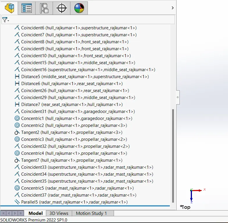
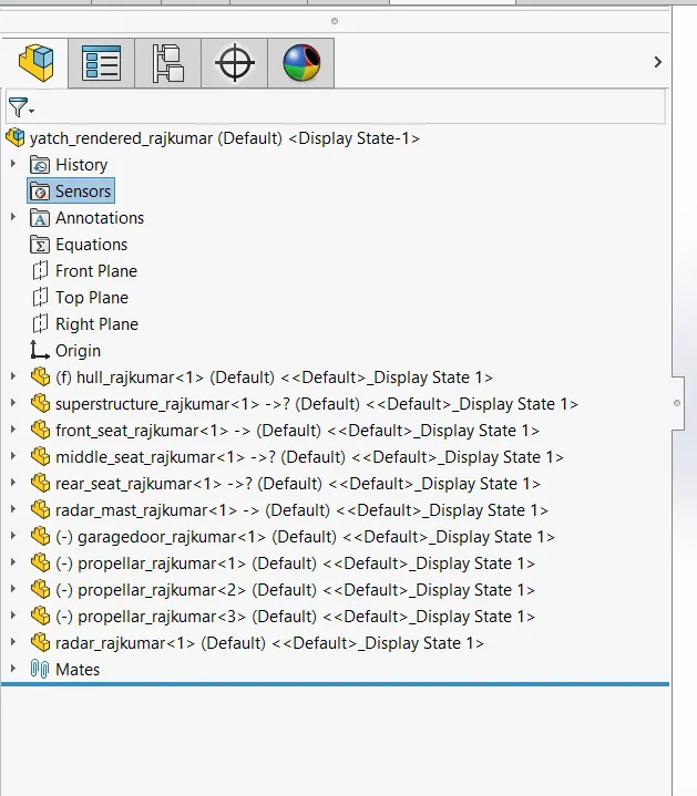
Import all the parts physically by utilizing Insert Components option. Then settle the Body portion by applying the coincident mate to the Best, Right and Front planes of the Gathering and Body respectively. Then for each portion apply the essential mates required by the Diagram utilizing Coincident mates, Point Mates, Separate mates etc.
RENDERING OF THE YACHT
Decals, cameras, lights, scenes, environment, and appearances are added accordingly.
CONCLUSION
The modelling of the predator yacht has been done successful.