Week 8 - Challenge 3 - Coin Holder Design
REPORT WRITING
CONTENTS
- TOOLING AXIS
- BISECTING METHOD
- DRAFT ANALYSIS
- B SURFACE
- C CURFACE
TOOLING AXIS
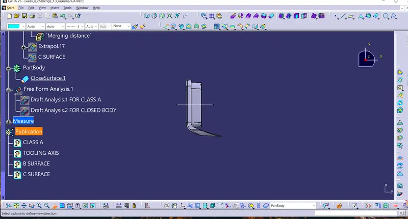
The course in which the form open and closes is called the tooling hub direction. Check the network of the surface and guarantee there will be no crevice between the surfaces and after that characterize the tooling axis. While making a tooling hub if it's not too much trouble guarantee to deliver the tooling hub on a level length surface or the surface which have a gap on it. Create a point on the center of the base surface by utilizing point on the surface command at that point make a crossing point for the surface and extract the reference lines which is able be supportive for making the sham tooling pivot utilizing the meet strategy by making a bisecting line.. Use the line command and draw the lines which is adjusted with the extricated lines and expanded it to the specified length.
BISECTING METHOD
Recognize on which plane we got to do more operations and make the plane or pivot on the component region characterize it on the sham tooling axis direction. Intersect the lesson A surface with that plane at that point we'll get a crossing point outline. Search for the profile (slanted line) which can make a issue and extricate it at that point amplifying it by using line command. Then make a bisecting lines with reference to the lines we have expanded and this will be our primary tooling axis. In this case we have made tooling hub beside Y heading with reference to the base surface.
DRAFT ANALYSIS
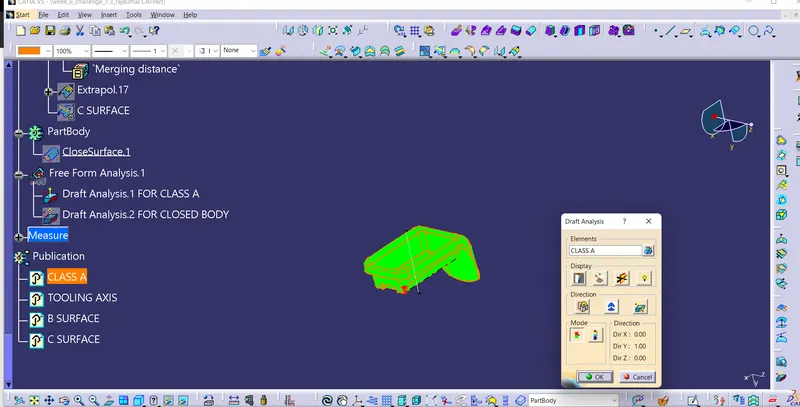
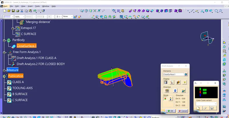
Draft permits for the component to discharge from the form, most parts or applications require a least of 0.5 to 1 degree draft point and 3 dgree draft point is broadly utilized as per the norm. Change the fabric mode to customize mode some time recently moving to the draft analysis. Insert –analysis-feature draft analysis Defining the draft course Select draft investigation from the instrument bar and press on the compass image and drag the compass from the correct side best corner of the workbench and put it on the component where need to do the draft investigation. ‘W’ of the compass and tooling hub ought to be adjusted on the same line. Once the compass is adjusted with the tooling pivot tap on the bolt image and drag on the surface we'll get a off-base stamp at that point select that point a table will show up it appears the draft esteem on the table we will alter the draft value and investigation it for all the edges and surfaces. By clicking the on the surface and utilizing the flipping instrument able to relegate the Flipping heading.
B SURFACE
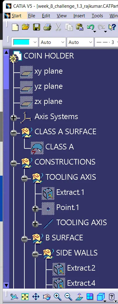
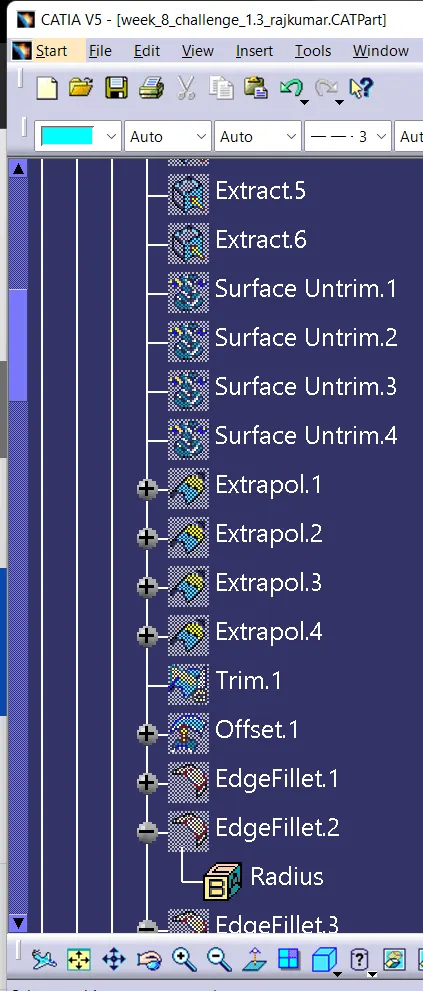
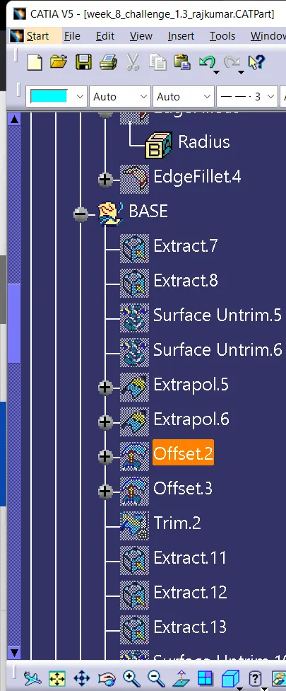
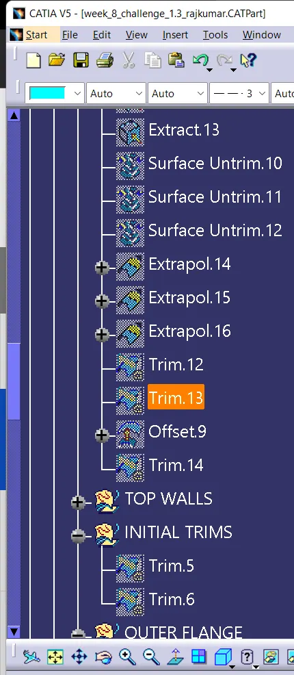
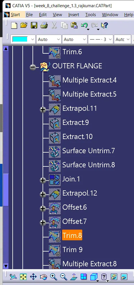
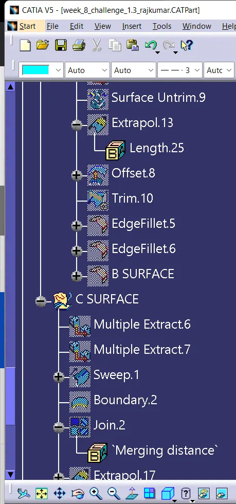
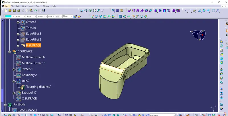
Within the case of Lesson A the surface underneath is called center and the surface over is called cavity. Class A is an aesthetics surface and course B is an building surface. B surface ought to be interior the lesson A surface. B surface can be isolated into four surfaces the side dividers, best dividers, external spine and the base surface and afterward trim them altogether. First step is to form the side divider surfaces by extricating the desired surface from Class A and untrimmed it thus we are going get a single surface which can be extrapolated to induce the desired measure and at last counterbalanced it to the inward side of course A as per the thickness of the fabric and trim them together and apply the specified filet by measuring the values from lesson A. Base surface of the component is at that point extricate, untrimmed, extrapolated, balanced and trimmed. The best dividers can be specifically extrapolated from the extricated surfaces and balanced it for the desired estimate of the material. Then connect the base, side divider and beat divider by trim.
C SURFACE
CONCLUSION
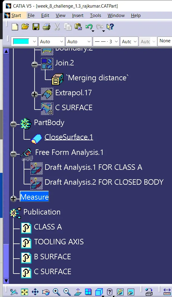
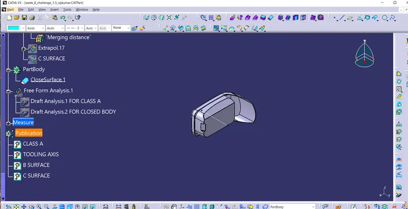
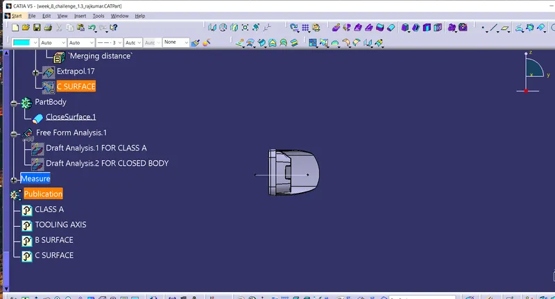
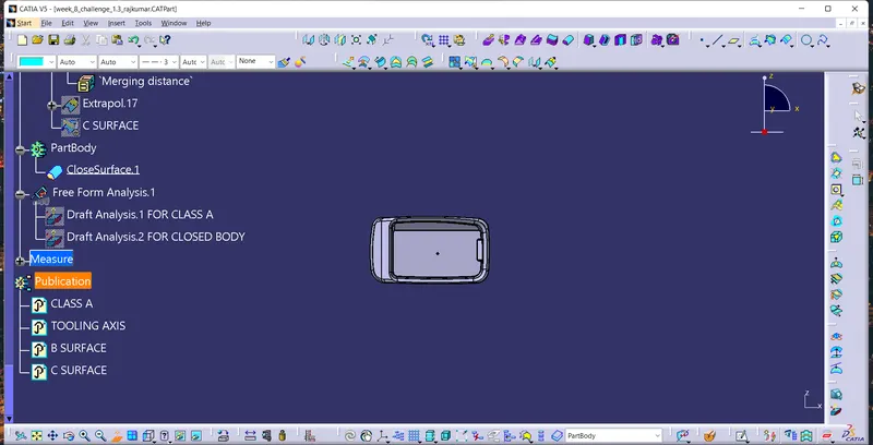
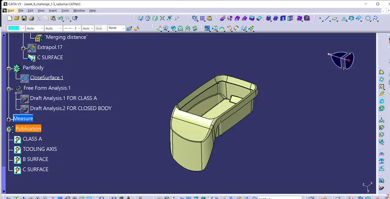
Thus creation of B SURFACE,C SURFACE,And closed body is achieved.