Week 8 - Challenge 1 - Base Bracket Design
REPORT WRITING
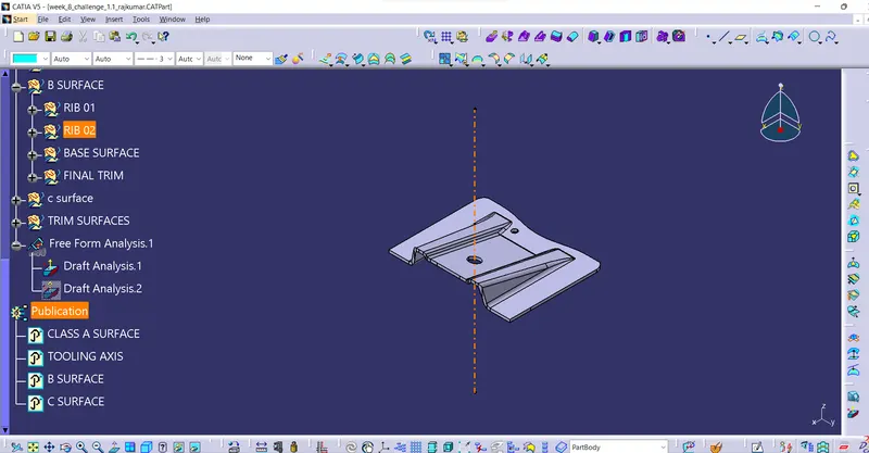
AIM: Make the Base Bracket Plastic component through the given Class-A surface. To start with, the tooling axis for the given Class A Surface ought to be made assembly the prerequisites of the draft point and at the conclusion perform the Draft investigation on the demonstrate
TABLE OF CONTENTS
- Check the connectivity of the Class A Surface
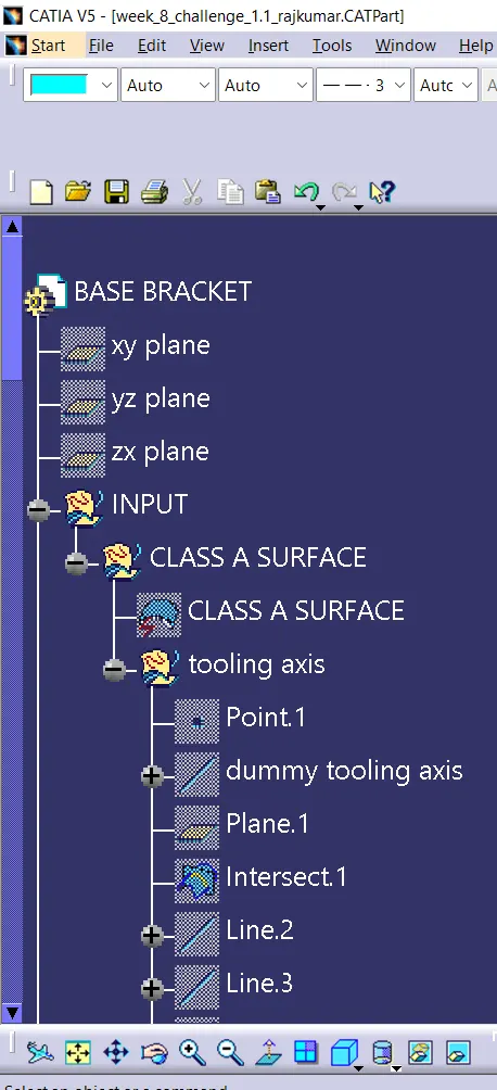
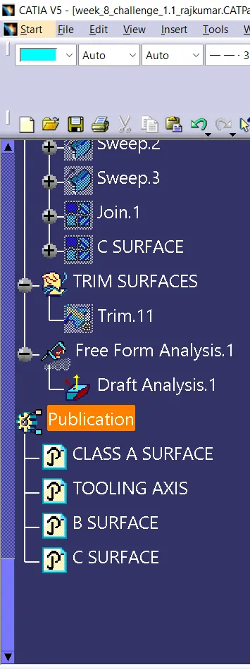
- The tooling axis
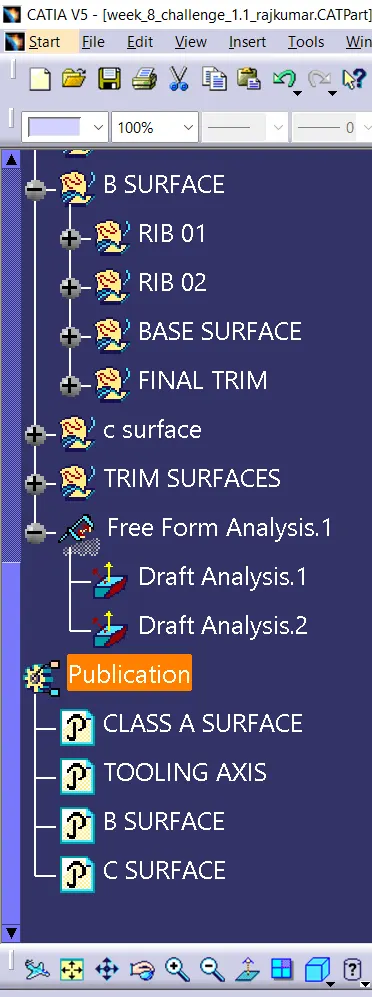
- Creating Class B Surface
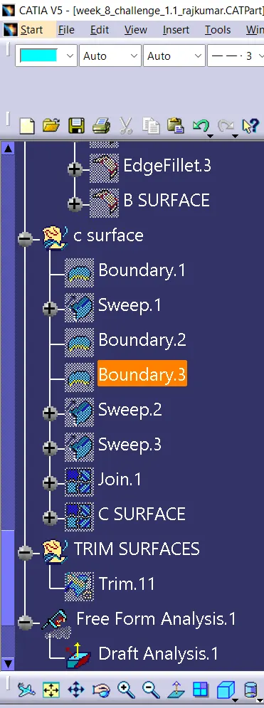
- Creating Class C Surface
- BISECTING METHOD
Check the connectivity of the Class A Surface
Guarantee that there's no crevice between the component, utilizing join command. We can outwardly check it or by clicking boundary command. It has 3 boundaries one external and two inward circle boundaries. Therefore to begin with check completed.
THE TOOLING AXIS
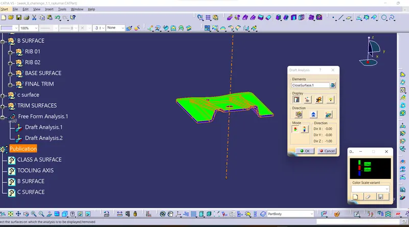
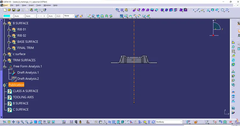
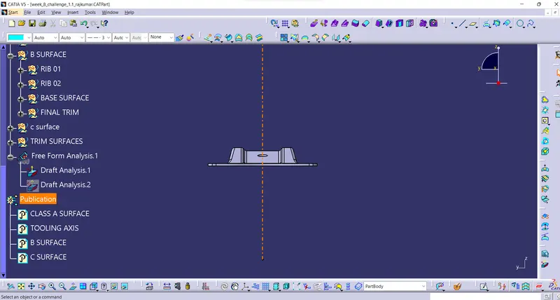
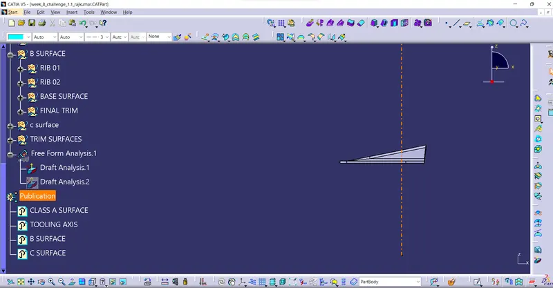
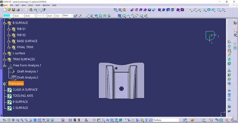
The tooling axis is nothing but the form opens or depth opens. Check visually which is the finest conceivable tooling axis. Check all three axis. Along x it conceivable but expensive and y isn't possible. z is the leading conceivable tooling axis. Therefore the most tooling hub is along z axis. Now perform the Draft investigation utilizing the Highlighted Draft Examination device within the tools. Then after opening the draft examination instrument box go for the compass and put the compass aligned to tooling hub and tap on the bolt image after aligning and assist tap on the surface.
CREATING CLASS B SURFACE
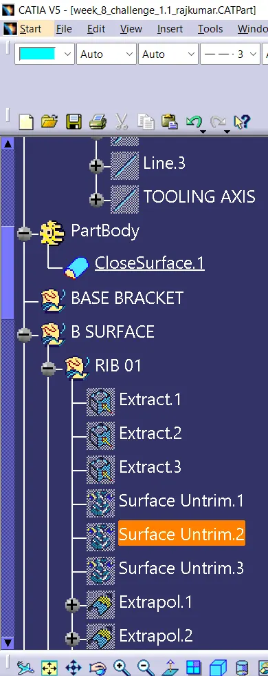
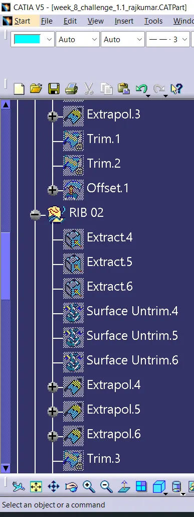
Initially extricating the proper side rib utilizing extricate alternative from Course A surface. Then perform Extrapolate in order to extend the length Now trim the surfaces to required surfaces Then Balanced the surface in order to urge the desired thickness Similarly make the cleared out side rib Now Similarly get the slanted as well as the level surface and balanced it to craved value And presently trim in order to urge the desired surface Now filet the surface to required sum.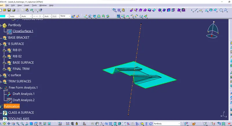
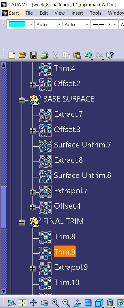
To form the class B surface, I considered the complete surface has 3 parts 'Rib-1, Rib-2, and Base surface'. On the off chance that we specifically counterbalanced the course A surface, filets may lead to cause an blunder, to dodge the blunders we ought to extricate the surfaces and untrim the extricated surfaces and extrapolate those untrimmed surfaces with point coherence. Presently trim those extrapolated surfaces to the specified shape. And at long last, filets were given to the ultimate trim.
DRAFTING ANALYSIS
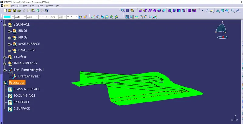
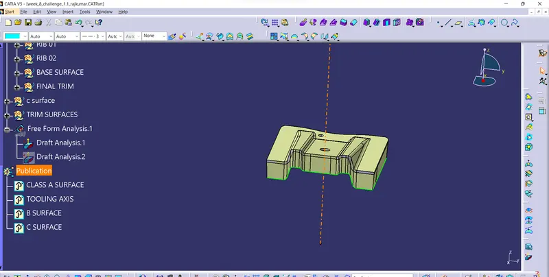
Once the draft analysis toolbar is opened, go to the show piece and select the 'Analysis beneath the running point' command to check the point for diverse sides (ribs and slanted plane points) on the lesson A surface. The color scale on the foot visualizes, whether the draft point meets the necessities or not (3 deg) by demonstrating the colors Green, Blue and Ruddy. Once the draft point examination was done, we ought to adjust and settle the compass to the tooling hub of the course A surface.
BISECTING METHOD
Bisecting strategy is essentially utilize to discover the correct tooling pivot utilizing the sham tooling pivot. In Bisecting strategy, bisecting line is utilized which either bisect the two line or it'll appear mistake which suggests the two lines are parallel to each other. In arrange to know whether the specific surface is toolable or not we meet the surface with the respective plane and get a portray which comprise of two lines and with the assistance of bisecting line choice we separate the line which makes a line at the mid point of the two lines. Like wise we make tooling clearing hub for x and y which is able be utilized to form the most tooling pivot utilizing the bisecting line alternative in within the line comand.
CONCLUSION
Thus the drafting of the class A surface and the final component is achieved.