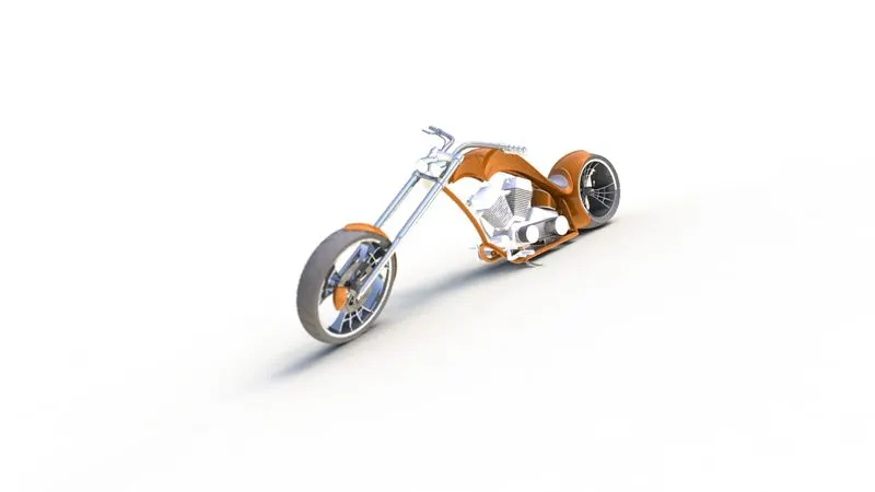
Photo Realistic Rendering
ASSEMBLING OF AMERICAN CHOPPER
OBJECTIVE
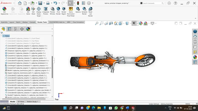
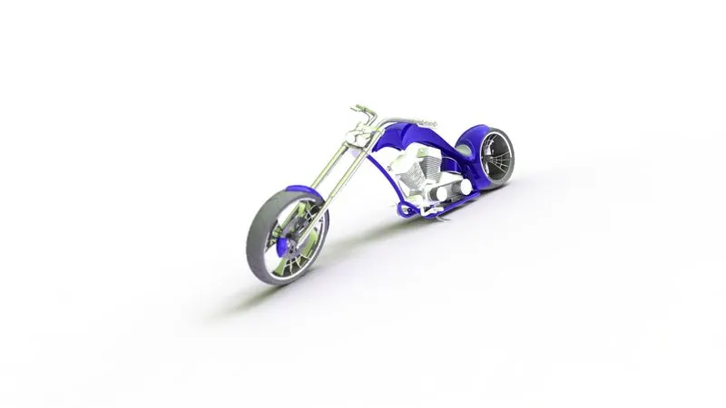
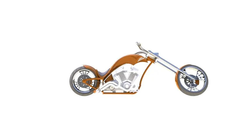
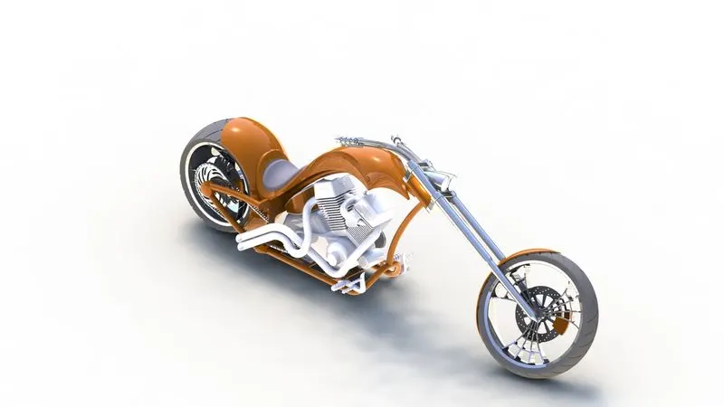
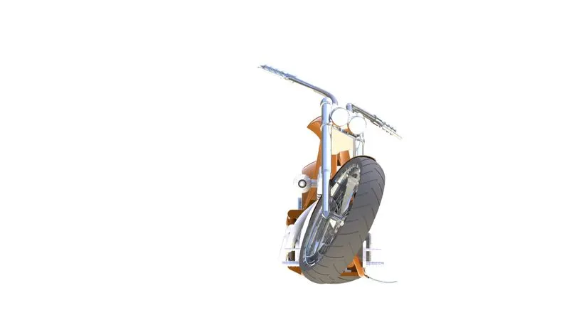
In this report we are going to assemble a American chopper and add rendering features to it.
INTRODUCTION
In this course we will learn the fundamental tools and concepts for the solid works engineering and design software. solid works is one of the largest computers aided design (cad) software globally used across numerous industries including manufacturing, automotive, aerospace, defence, medical devices, robotics & automation, consumer products, construction, and many more!
This course will run through the core concepts and tools available within SOLIDWORKS to help us design and build any parts, drawings, and assemblies we may require for our specific projects.
We will start by getting comfortable with the user interface and work-space of SOLIDWORKS, move onto creating our first sketch and design our first parts. Once we have learned several the core part design tools, we will introduce drawing tools to generate technical or engineering drawings required to manufacture our parts. Finally, we will learn assembly tools to help us design and build our assembly projects that contain multiple components.
Choppers bicycles are bikes included on the tv arrangement of American Chopper for a particular corporate or celebrity client. The work of bike ordinarily takes a rearward sitting arrangement to the introduction of the topic, and these bikes pull in consideration exclusively on the preface of the topic itself.
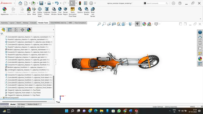
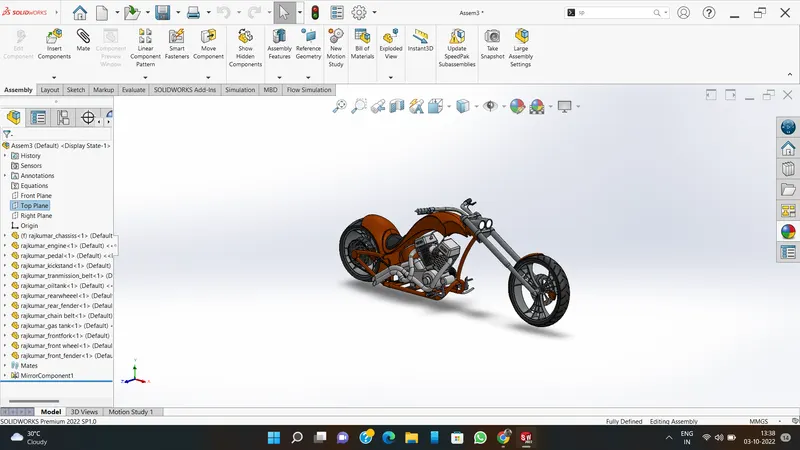
After modelling of each component, each part is brought to one assembly file and then assembled by providing required constraints or mates relation to each component in assembly environment of the SolidWorks.
The main parts of chopper are: The following parts of the chopper are used for model and assembly in solid works.
- Transmission belt
- Kick stand
- Front fender
- Rear fender
- Oil tank
- Chain
- Pedal
- Front wheel
- Rear wheel
- Front fork
- Chassis
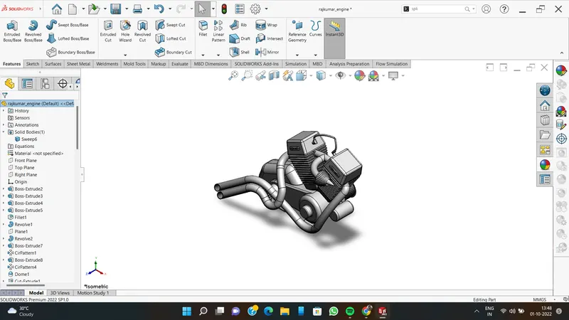
- Engine
- Gas tank
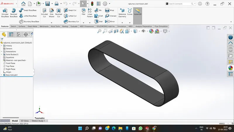
- Transmission belt
The most reason of transmission belt is utilized to transmit control which is created interior the motor to adapt box with greatest effectiveness.
FEATURES USED
- Sketch
- Offset
- Extrude
- Fillet
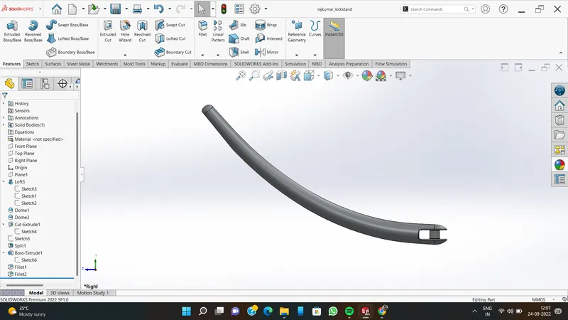
- Kick stand
A kickstand may be a gadget on a bike or bike that permits the bicycle to be kept upright without inclining against another protest or the help of an individual. A kickstand is ordinarily a bit of metal that flips down from the outline and contacts the ground.
FEATURES USED
- Sketch
- Loft
- Dome
- Extrude boss
- Extrude cut
- Fillet
- Split
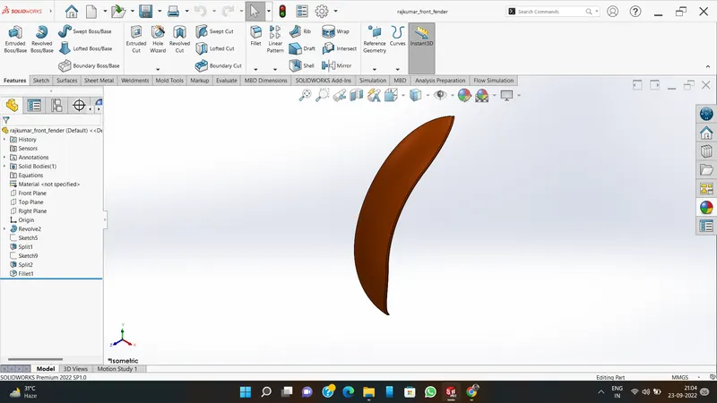
3.FRONT FENDER
A fender is essentially a covering for your bike tires that protects you from the rain. Riding with fenders will prevent the rain from splashing a streak of muddy water up your back, over your shoes and on your face.
FEATURES USED
- Sketch
- Offset entities
- Trim entities
- Revolve
- Dynamic mirror
- Split
- Fillet
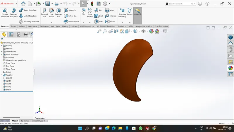
- REAR FENDER
Its primary purpose is to prevent sand, mud, rocks, liquids, and other road spray from being thrown into the air by the rotating tire.
FEATURES USED
1.Sketch
2.Offset entities
3.Trim entities
4.Revolve
5.OIL TANK
An oil capacity tank could be a container or store that briefly holds oil within the different stages of handling into other oil items, or some time recently it is utilized or devoured. Based on area, oil capacity tanks may be classified as surface or over ground, semi underground and underground or underground tanks.
FEATURES USED
1.Sketch
2.Boss extrude
3.Combine
4.Shell
5.Fillet
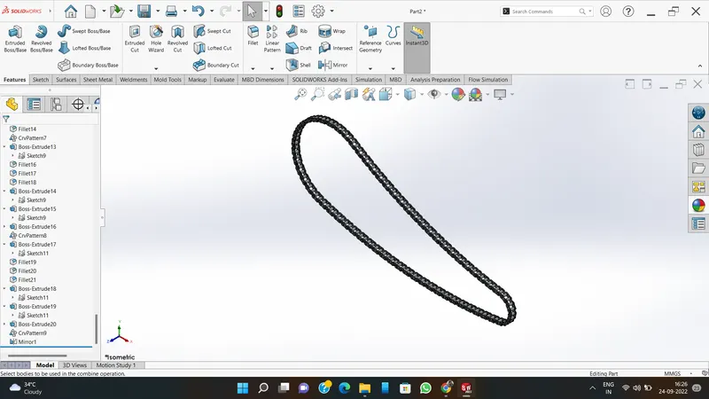
6.CHAIN
Chain drives are most utilized to transmit control between two components that are at a more noteworthy separate, but they may too be utilized for brief separations. They are one of the five most regularly utilized mechanical control transmission strategies nearby shaft couplings, adapt drives, belt drives and lead screws.
FEATURES USED
- Sketch
- Boss extrudes
- Fillet
- Curve driven pattern
- Mirror
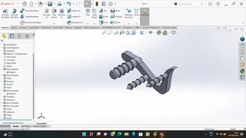
7.PEDAL
The pedal is the portion of a bike that the rider pushes with their foot to impel the vehicle. It gives the association between the motorist 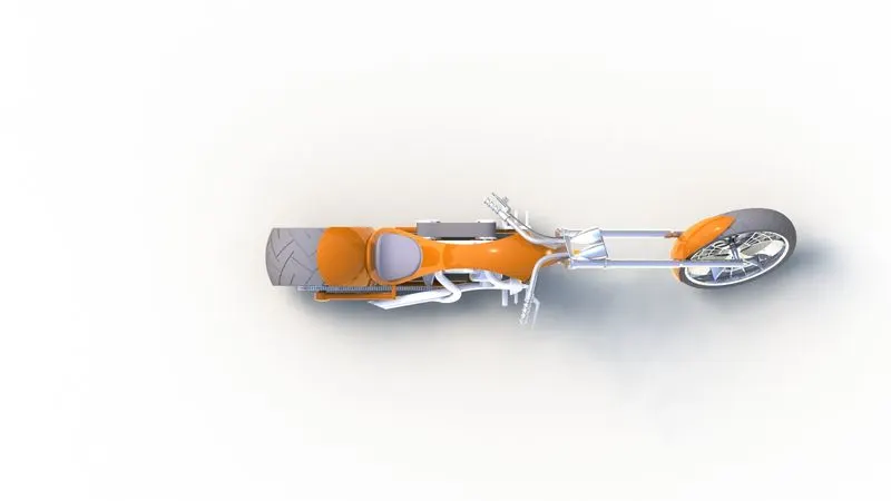 foot or shoe and the wrench permitting the leg to turn the foot bracket axle and move themotorcycles wheels.
FEATURES USED
- Sketch
- Boss extrudes
- Revolve
- Dome
- Fillet
- Chamfer
- Linear pattern curve
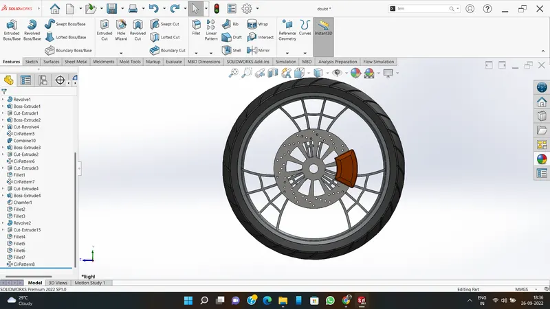
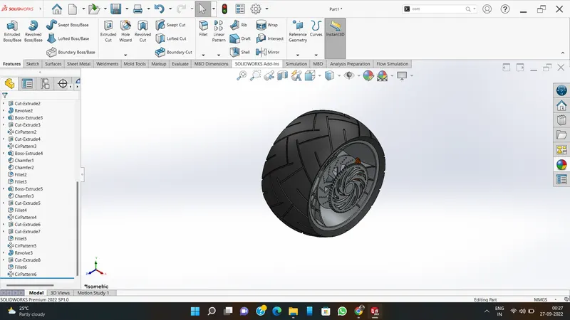
- FRONT WHEEL & REAR WHEEL
Wheels, in conjunction with axles, permit overwhelming objects to be moved effectively encouraging development or transportation whereas supporting a stack, or performing labour in machines. Wheels are moreover utilized for other purposes, such as a ship's wheel, directing wheel, potter's wheel, and flywheel.
FEATURES USED
- Sketch
- Revolve
- Boss extrudes
- Cut extrude
- Circular pattern
- Linear pattern
- Combine
- Trim
- Fillet
- Chamfer
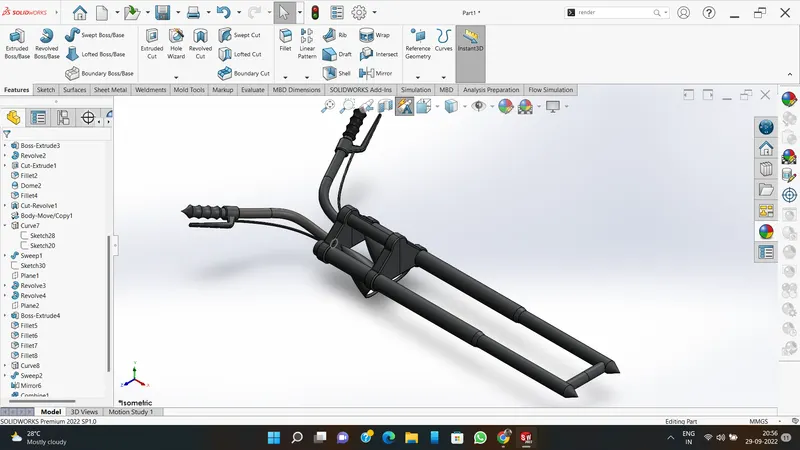
9.FRONT FORK
Most forks incorporate the front suspension and front brake, and allow the front wheel to rotate about the steering axis so that the bike may be steered.
FEATURES USED
- Sketch
- Revolve
- Boss extrudes
- Fillet
- Linear pattern
- Cut extrude
- Dome
- Revolve cut
- Project curve
- Mirror
- Combine
- Sweep
- Split
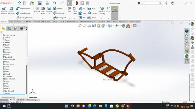
10.CHASSIS
The chassis provides the strength needed for supporting the different vehicular components as well as the payload and helps to keep the automobile rigid and stiff. Consequently, the chassis is also an important component of the overall safety system.
FEATURES USED
- Sketch
- Convert entities
- Project curve
- Offset
- Trim
- Sweep
- Split
- Revolve
- Cut extrude
- Fillet
- Combine
- Mirror
- Chamfer
- Dome
11.ENGINE
An engine is some machine that converts energy from a fuel to some mechanical energy, creating motion in the process. Engines - such as the ones used to run vehicles - can run on a variety of different fuels, most notably gasoline and diesel in the case of cars.
FEATURES USED
- Sketch
- Boss extrude
- Revolve
- Fillet
- Circular pattern
- Dome
- Cut extrude
- Chamfer
- Linear pattern
- Mirror
- Swept
- Project curve
- Split
12.GAS TANK
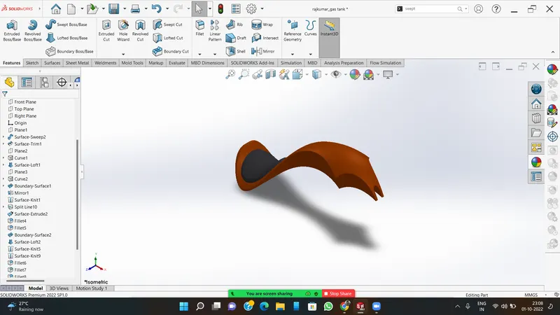
A fuel tank (moreover called a petrol tank or gas tank) may be a secure holder for combustible liquids. Although any capacity tank for fuel may be so called, the term is ordinarily connected to portion of a motor framework in which the fuel is put away and impelled (fuel pump) or discharged (pressurized gas) into an engine.
FEATURES USED
- Sketch
- Surface sweep
- Surface trim
- Project curve
- Surface loft
- Surface boundary
- Surface knit
- Split line
- Mirror
- Surface extrudes
- Fillet
- Cut sweep
- Shell
RENDERING FEATURES
SOLIDWORKS Visualize provides industry-leading rendering capabilities with visual design-oriented features and workflows in place. This allows for fast and easy creations of visual content that communicates a designer's vision and showcases your part in the most stunning way.
ASSEMBLEY SECTION
The parts are assembled by using mate’s option.
CONCLUSION
A demonstrate has been created with the assistance of Solid works by utilizing a few worldwide factors, dimension, and equation.
- The clients can upgrade show fair by changing ground clearance, Tire estimate, etc.
- In this way architect can perform assignments particularly within the mechanical design.
- After this client are comfortable to plan and adjust distinctive components.