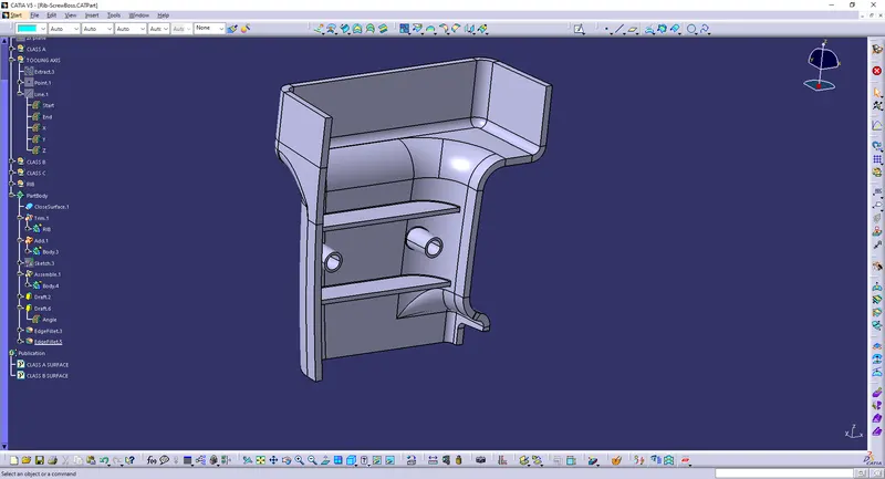
Week 9 - Attachment Feature Creation (Ribs & Screw Boss) - Challenge 1
AIM:Create the rib for the Drill Handle considering the design rules
PROCEDURE:
Part I
* Import the .STEP file into CATIA V5.
* fit the object to screen. Save the file into CATPART
*Open the file save it.
*use varnier tool to check the flat surfaces.
CREATING TOOLING AXIS
*By changing orientation and select a axis at which maximum part is visible.
*choose a surface and use point [•]
point >on surface >select a Surface >'0'
Choose line [/]
line point-direction select points Select axis
* The created line is the tooling axis Publish it.
Part II:
Offset → select the Class A Surface
*Click on the other side, so we obtain the.offset of A surface of 3mm which is considered as class B
*Fillet all the edges of required dimension
*class B surface is ready - Publish it
Part III:
* Make surface A visible and make boundary limit as required.
Sweep-> Using boundary and surface>90>and give okay
Now Join the Surface A &C.
*Use extrapolate . and completely check there is no open boundaries
*C surface is created and Join A+c and publish it
*Make the b surface visible and just extrapolate the extra edges
*Trim the extra surfaces and the required part of 3 mm thickness is created
*Go to Part Modelling Close surface → fill
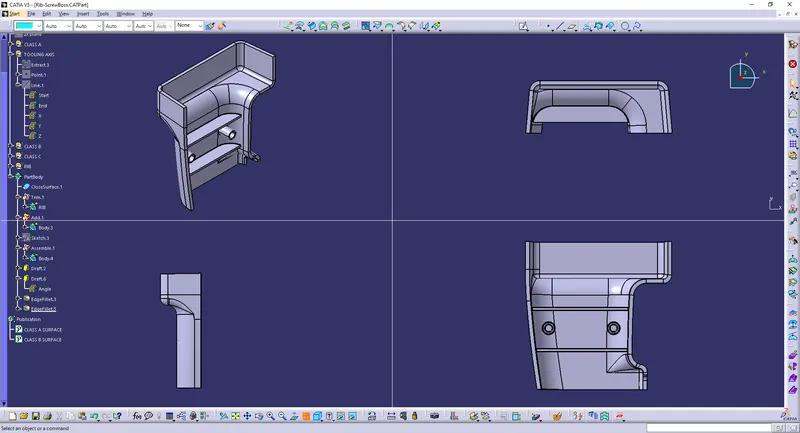
* So the surface model is converted into part model.
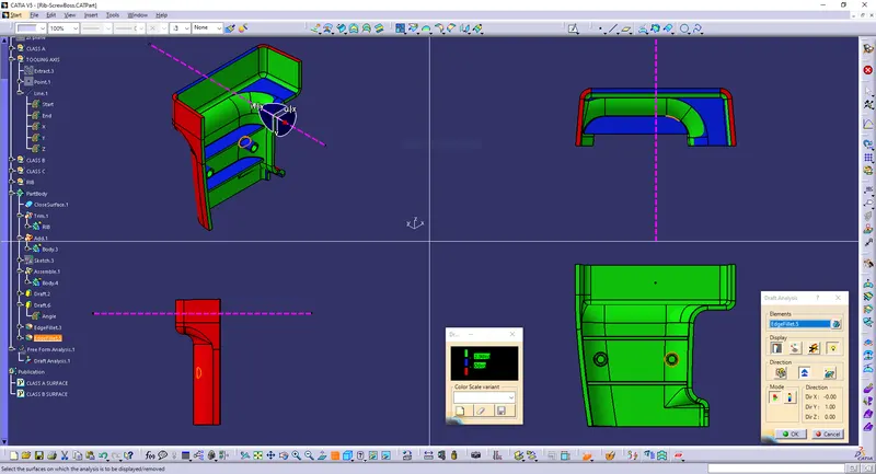
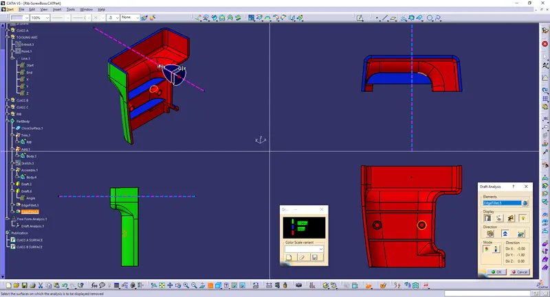
Draft Analysis is made on both sides "3"
Challenges:
During offsetting the untrim or Extrapolated region,the wrong surface is created and it's difficult to sort out on which side the offset must be.
Trimming the excess area, affects the original surface.
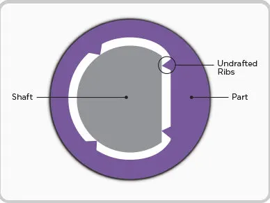
Guidelines for Injection Molding Crush Ribs
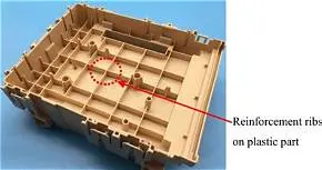
Ribs are more or less thin extensions, often at right angles from the wall or plane of the plastic parts. Below are some helpful crush rib guidelines:
- Fabrication of ribs with minimal thickness is essential for preventing thick parts of the wall base.
- To reduce sink marks, use ribs of about 60 percent of the joining wall thickness.
- Use suitable draft angles.
- For effective practices, increase spacing to about two times the wall thickness.
- When walking with glossy materials, use thinner ribs – about 40 percent wall thickness.
Options for Draft and Tight Fit Besides Adding Crush Ribs
Well-structured plastic injection molded parts and designs often have drafts, as they are necessary to quickly eject these parts from the mold. However, these drafts may account for weakening the press fit parts. Hence, the addition of ribs proves to be a better and more effective means of working with press fits components.
Should you choose not to use them in your design, below are other options that will provide a tight fit to your press fit connections.
Leave the hole as-is
This option may be risky, though it could be effective if correctly done. During molding, the molder needs to support the zero draft. The hole size mentioned is a factor as shallow holes pose fewer difficulties, but deeper holes require more stress to the mold’s cores during cooling and ejecting.
Increasing the ejection force may lead to the breakage of the core or ejector pins. Consequently, the molder may need to tweak some of the process parameters to prevent mold damage. However, this risks complications like porosity and weak knit lines. This option is quite complicated and requires a high level of expertise. Hence, manufacturers may need to consider other options before proceeding with.
Boss Configurations Vary on Plastic Parts
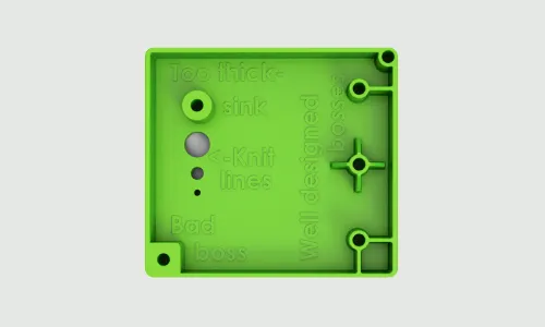
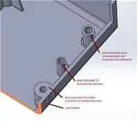
A typical boss is an open-topped cylinder, essentially a round rib. Standard guidelines suggest that its wall thickness be between 40 and 60 percent of the thickness of the wall from which the boss rises. If your design requires more strength than this guideline would provide, you should consider ways to strengthen the boss without thickening its walls. The most common of these is to surround the boss with gussets to support and strengthen its walls.
If a boss is part of a vertical wall, it should not create a thick area in the wall. Similarly, if a boss is located close to a vertical wall, it may be tempting to tie the boss to the wall by filling the space between the boss and the wall, resulting in a thick area. A better way to tie the boss to the wall is with one or more ribs.
In some cases, Protolabs’ milling process may require that the walls of the boss be thicker than the standard 40 to 60 percent mentioned above. Unlike steel tools, which can use steel core pins to form the inside diameter of a boss, Protolabs forms both the outside diameter and the inside diameter of a boss with features of the aluminum mold. When cutting a mold for a relatively tall boss, we may not be able to use a sufficiently small-diameter cutter to create walls that thin. You can avoid the problem by reducing the height of the boss, allowing the use of smaller-diameter cutter. Or you may find that a small amount of sink in the wall surface opposite the boss is acceptable.
Other Considerations for Plastic Boss Design
There are two additional points to consider in designing bosses. As mentioned earlier, a boss is a circular rib, and like any rib, its walls—both inside and out—must be drafted to facilitate ejection. Depending on the height of the boss, this draft can be anywhere from a half degree to 3 degrees. If draft of the inside diameter of the boss is not acceptable, the boss can be molded as a solid and the inside diameter drilled, by you, as a secondary operation. Also, because a boss is formed by a blind hole in the mold body, we may have to add vent pins to the rim of the boss to allow the escape of trapped gas during mold filling. Otherwise shorts or burns may form on the rim.