Week 9 - Attachment Feature Creation (Ribs & Screw Boss) - Challenge 1
Aim: To Create rib and Screw boss for teh door handle considering the design rules
Objective:
- To create Tooling axis for the given Class A Surface
- To create Class-B and Class-C surface for the Door Handle
- To create Final closed surface and the final solid body of the Door Handle
- To Create Rib and Screw Boss on the Class B surface by considering the desing rules
- To perform the draft analysis on the Class A Surface and the Final Solid body
Class A Surface: Surface made by the designer which is given as the input to work on it. It is an asthethic surface.
Class B Surface: Class B surface is created in a certain distance according to the thickness of the part. Class B surface contain all the engineering components.
Class C Surface: Class C surface joins Class A surface and Class B surface.
Class A Surface
- Firstly, the 3D CAD file of the Class A Surface is downloaded.
- Next step is to check the continuity of the Class A Surface. This is to ensure that there is no gap in between surfaces.
- Firstly, visually inspect the Class A surface and then apply the Boundary or Join command on the Class A surface to make sure there is no gap in between the surfaces.
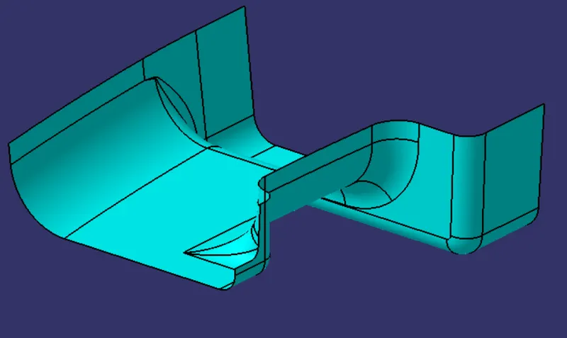
Figure: Class A surface
Tooling Axis:
- Tooling axis represents the opening and closing of the mold core and cavity during the manufacturing of the components. A plastic product designer should consider the best tooling direction to cutdown the cost of the component very less.
- Firstly, check visually for the best possible tooling axis and we find from the Y-direction it is most convenient.
- Using the Extract command, extract the appropriate surface and next further create a midpoint on the extracted surface
- Create a line normal to the exrtacted surface along the Y- direction with the point as the reference. This created line named as "Tooling Axis".
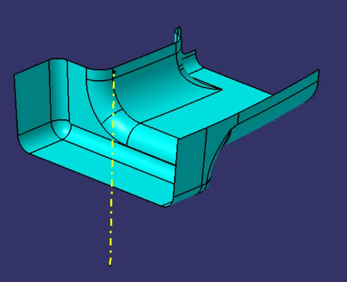
Figure: Tooling Axis
Draft Analysis on Class A Surface:
- The Draft Analysis allows the user to easily analyses the proper draft angle and manufacturability of the designed component.Draft analysis is done after determining the tooling axis, draft analysis is used to check whether the minimum draft is maintained or not.
- Firstly change the viewmode of the component in the customized parameter mode and apply the Draft Analysis Command on the Class A surface
- Then drag and align the compass on the tooling axis and lock the compass
- Perform the draft analysis by clicking on the component
- The green colour shows the positive draft tooling direction and the given surface passes the draft analysis.
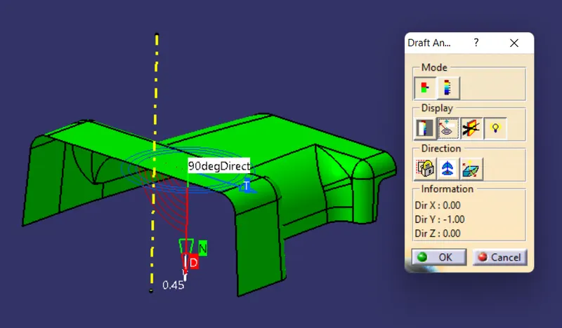
Figure: Draft Analysis on Class A Surface
Class B Surface:
- Offset the Class A surface to 2.5mm then we get the Class B surface with few patches in it.
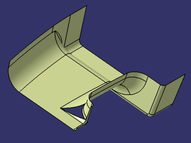
Figure: Class B Surface with patches
- Use the commands such as Extrapolate, Trim, Multi-section surface, Fill to clearout the patches
- Finally, Class B surface is created
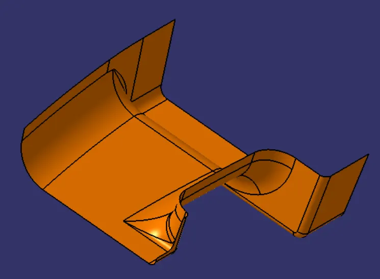
Figure: Class-B surface
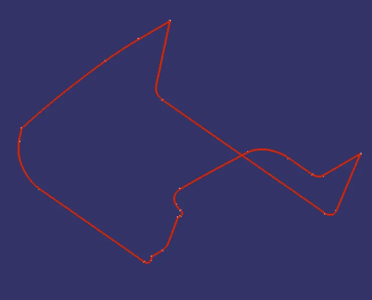
Figure: Class-B Surface Boundary
Class C Surface:
- Extract the Outer boundary of the Class A Surface
- Using the Sweep Command, sweep the boundary with reference to the boundary as the guide curve and the Class A surface as the Reference Surface at 90 degrees and of 4mm length.
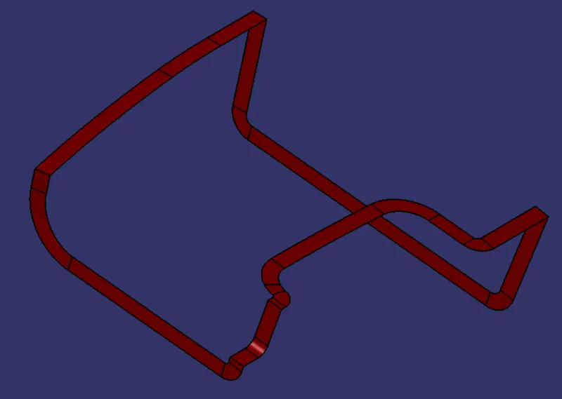
Figure: Class C Surface
- Further Join the Class A and Class C Surface
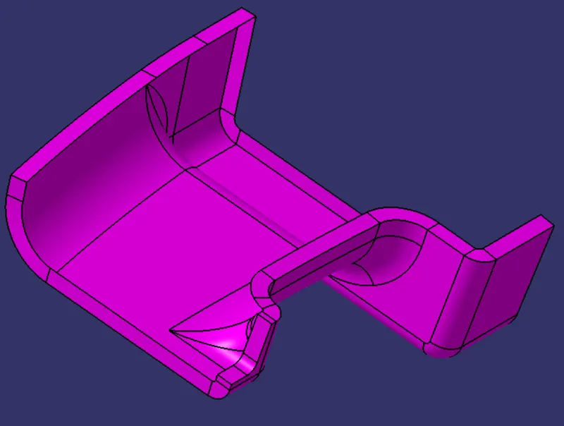
Figure: Class A+C Surface
Final Closed Surface:
- Using the Trim Command, trim the Class A+C Surface and Class B Surface to get the Final Closed Surface.
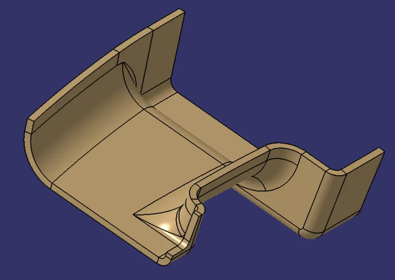
Figure: Final Closed Surface
- Switch to the Part Workbench, apply the Closed Surface Command on the final closed surface to create the Solid body.
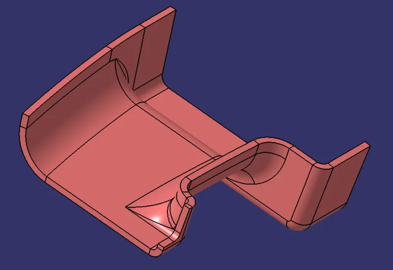
Figure: Final Closed Partbody
Ribs and screw bosses are engineering features which are created on the B side of the plastic components.
RIBS
Ribs are used to strengthen the walls of your mould without increasing wall thickness which means that we minimise the problems that come into play when the wall thicknesses have to be increased. If the wall is considered too thick, warping and sinking can result so that the entire design may need to be rejected.
Procedure:
- Using the Multiple Extract Command, extract the base surface of the Closed surface
- Create a midpoint on the extracted surface
- Create a positioned sketch of the ribs by taking the created point as the reference
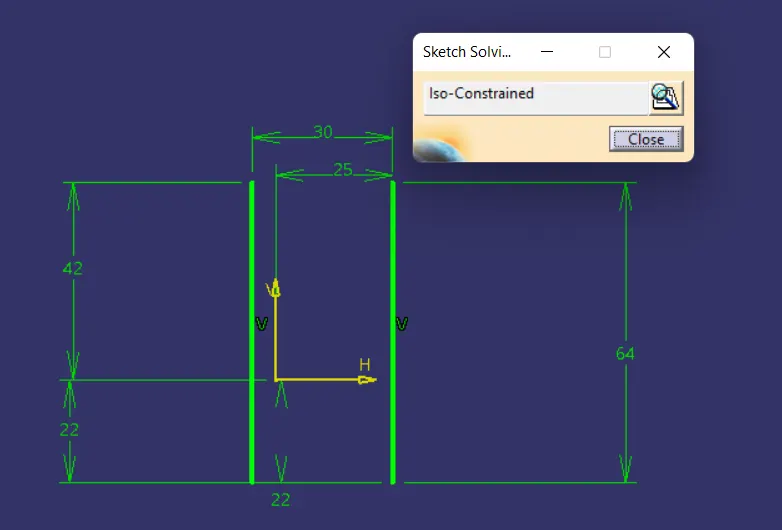
Figure: Sketch of the Ribs
- Further, Extrude the sketch with reference to the tooling axis and the Height of the rib as per the design rule must be 5* thickness of Partbody which can be altered by the length of the Extrude.
- Next switch to the Part Workbench and use the Thick Surface Command on the Extruded surfaces.
- Considering the Rib design rule the thickness of the rib must be 0.4* the thickeness of the Partbody
- Next Using the Draft command, a draft of 0.5 degree is applied on the walls of the ribs with reference to the Tooling axis as per the design rule.
- Ensure to Check the Rib tip thickness must be minimum of 0.75mm
- Next perform the Union Trim Boolean operation to add the rib body to the Part body of the Door Handle.
- Apply an edge fillet of 0.25mm on the edges of the Ribs and Finally do check the rib root thickness which must not be more than the 30% of the wall thickness.
- Spacing between the ribs must be in the ratio of 3:1 (Steel) and 2:1(Material) of Height:Width ratio as per the design rule
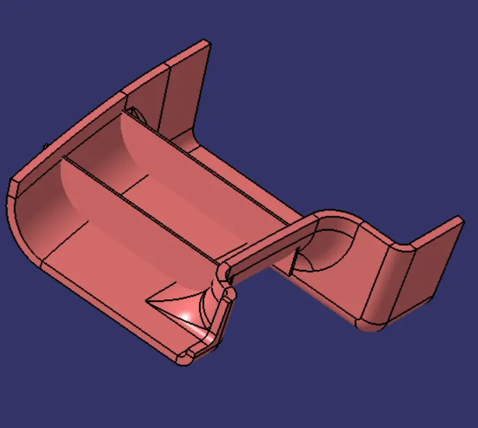
Figure: Partbody with Ribs as per the design rules
SCREW BOSS
Boss features are commonly found in injection molding designs. They are used to aid in the assembly of molded parts by providing a channel for a screw. Designing plastic screw bosses is fairly straightforward but there are a few considerations to ensure a strong connection between parts and mitigate cosmetic defects.
- Create a positioned sketch of Screw Boss and extrude the sketch with reference to the Tooling axis
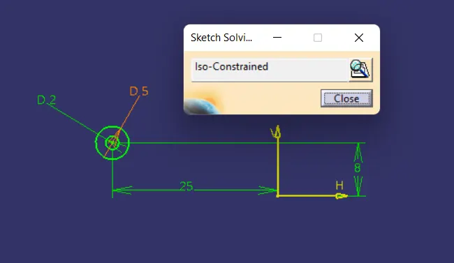
Figure: Screw Boss Sketch 1
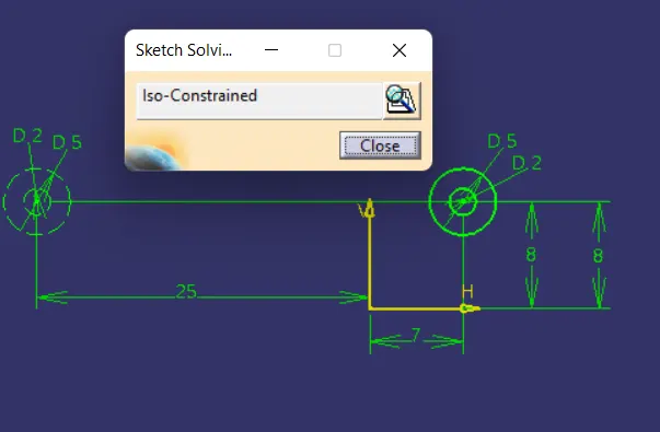
Figure: Screw Boss Sketch 2
- Switch to the Part Workbench and Use the Pad command on the Sketches
- Use Draft Command apply an draft of 0.5 degree on the both inside and outside faces of the screw boss.
- Use Edge Fillet Command and apply an fillet of 0.25mm on the inside and the outside faces of the screw boss
- Using Union trim Boolran operation add the screw boss to the Door Handle Partbody.
- Ensure to check the Height to Diameter ratio be 3:1 and remaining design rules are been followed during construction of the Screw Boss
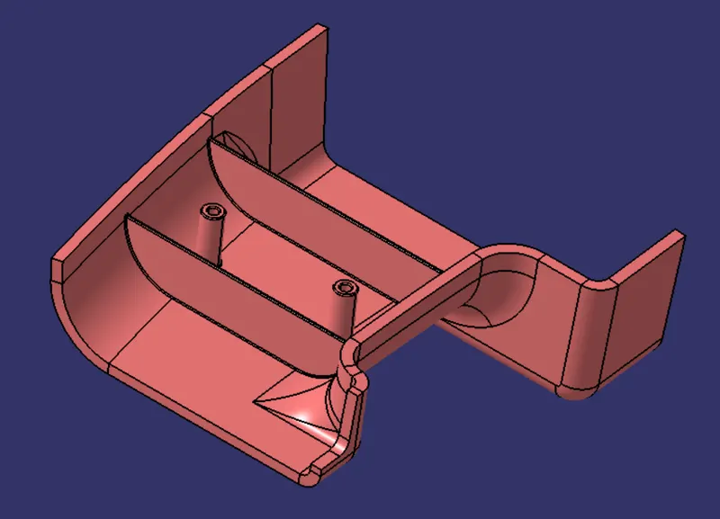
Figure: Door Handle with ribs and screw boss
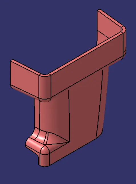
Figure: Isometric View of Door handle
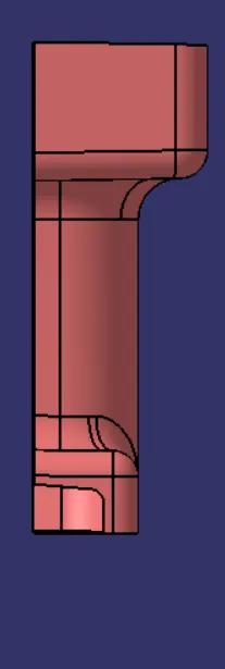
Figure: Front View of the Door handle
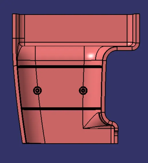
Figure: Side View of Door handle
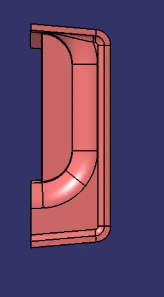
Figure: Top View of Door Handle
Draft Analysis on Final Partbody:
- Chnage the view mode of the component to be in customised parametermode and then select the shading mode as materials.
- Use the Draft analysis command and drag the compass and align it on the tooling axis.
- Further lock the compass and perform the draft analysis by clicking on the component.
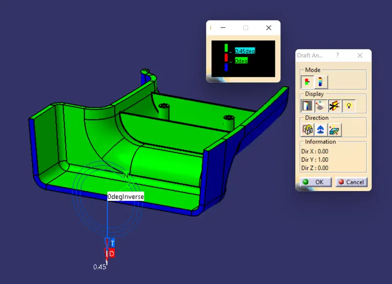
Figure: Draft Analysis on the Final Partbody
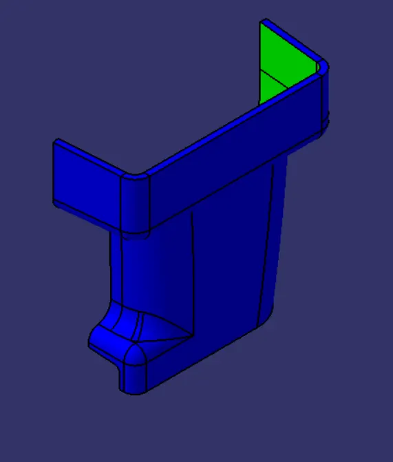
Figure: Isometric View
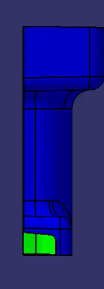
Figure: Front View
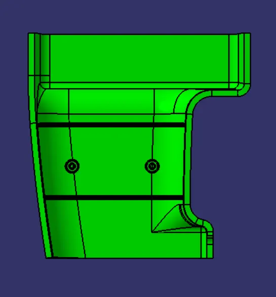
Figure: Side View
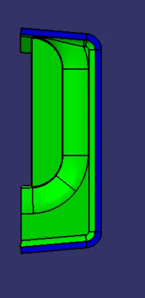
Figure: Top View
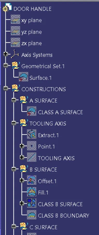
Figure: Expanded Tree (1)
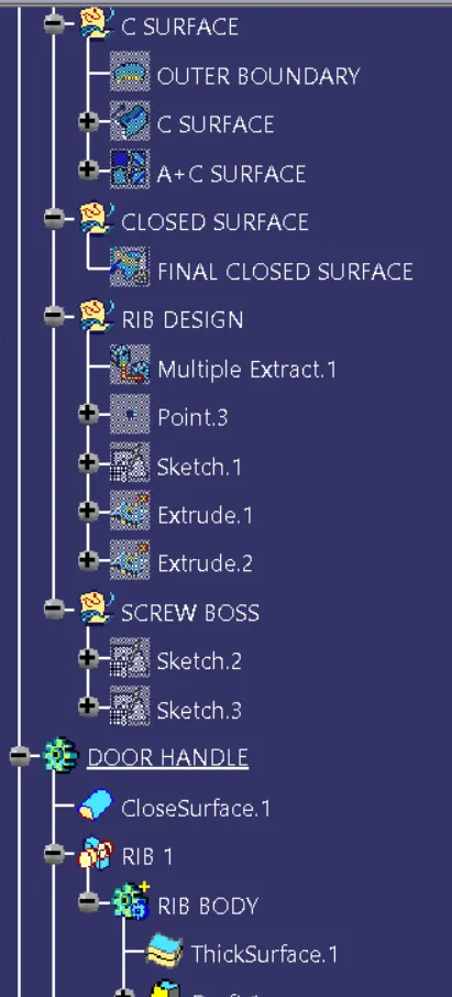
Figure: Expanded Tree (2)
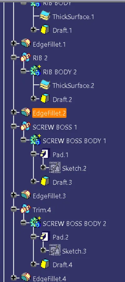
Figure: Expanded Tree (3)
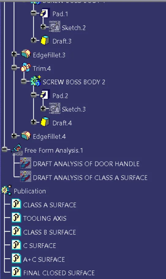
Figure: Expanded Tree (4)