Week 9 - Attachment Feature Creation (Ribs & Screw Boss) - Challenge 1
AIM:-Attachment Feature Creation (Ribs & Screw Boss)
Draft Analysis ?
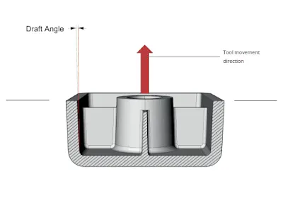
The Draft Analysis allows the user to easily analyze a part for proper draft angle. A Draft Angle describes the amount of taper for molded or cast parts perpendicular to the parting line.
Draft angles ?
Draft angles are very important in thermoforming product design. If the product is formed onto a female or negative mold, it shrinks away from the mold sidewalls. As a result, true female or negative products can be thermoformed with vertical walls having zero draft angles. If the product is formed onto a male or positive mold, it shrinks onto the mold sidewalls. A draft angle of 1–5 degrees is recommended for all male or positive products.
here we are taking minimum 7degree of draft angle because our die should not get damage and we should get a finish good product. In some area we cannot avoid negative draft. So bending operation is provided for the manufacturing process, because deep drawing cannot be done at the negative draft area.
Tooling Direction for Plastic Part
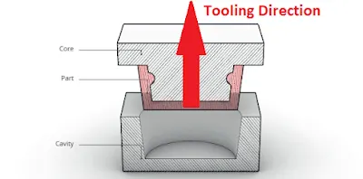
Tooling direction is main consideration for plastic part and mold parts because it defines movement of mold part and possibility of plastic part to come-out from mold part (Core and Cavity).
Tooling Direction:-
In Molding machine arrangement is given to open the mold along a direction which is known as Tooling Direction.
In other words. The mold is built from two separate halves (Core and Cavity) and tooling direction basically define the direction of mold pulls apart.
Tooling direction is known as primary direction.
WHAT IS CLASS A, B, C SURFACES ?
Class A:- Styling or A class surface are the terms used in plastic product design. That means the surface of a component that is smooth (aesthetic) or visible side to the human eye after the part is assembled.
Class B:- It is an engineering surface, and it gives you thickness from class A surface
Class C:- when Class A and Class B surfaces are joined along the tooling axis it is called class C surface.
WHAT IS RIBS ?
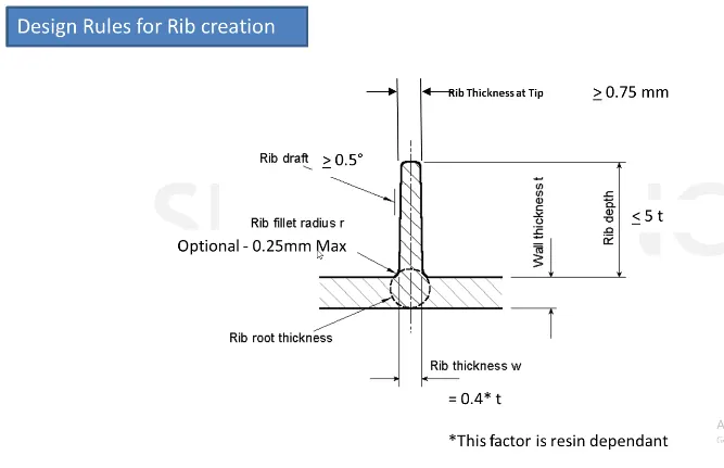
Ribs are a feature in plastic injection molded parts. They are thin extensions that run perpendicular from a wall or plane. They are commonly used to provide additional support and strength to a part.
Thickness and location are essential to rib design. Here are some helpful
- They should be designed with a thickness that is ½ the wall thickness to avoid a thick section at the wall base
- To minimize sink marks, design ribs that are approximately 60% of the joining wall thickness for minimum risk
- Best practices include spacing at a distance of at least twice the wall thickness
- Glossy materials require a thinner rib (40% of wall thickness)
WHAT IS BOSS ?
Bosses are projections designed to accept inserts, self-tapping screws, etc. for use in mounting, fastening or assembling parts
GUIDANCE FO BOSS
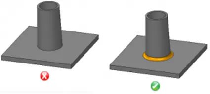
- Minimum Radius at Base of Boss
A fillet of a certain minimum radius should be provided at the base of a boss to reduce stress. The intersection of the base of the boss with the nominal wall is typically stressed and stress concentration increases if no radii are provided. Also, the radius at the base of the boss should not exceed a maximum value to avoid thick sections. The radius at the base of boss provides strength and ample draft for easy removal from the mold. The recommended value for radius at the base of a boss is 0.25 to 0.5 times the nominal wall thickness.
- Spacing between Bosses
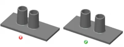
When bosses are placed very close to each other, it results in creating thin areas which are hard to cool and can affect the quality and productivity. Also, if the mold wall is too thin, it is very difficult to manufacture and often results in a lower life for the mold, due to problems like hot blade creation and differential cooling. Hence, it is recommended that spacing between bosses should be at least 2 times the nominal wall thickness.
- Radius at Base of Hole in Boss
Providing a radius on the core pin helps in avoiding a sharp corner. This not only helps to mold but also reduces stress concentration. It is recommended that the radius at base of hole in boss should be 0.25 to 0.5 times the nominal wall thickness.
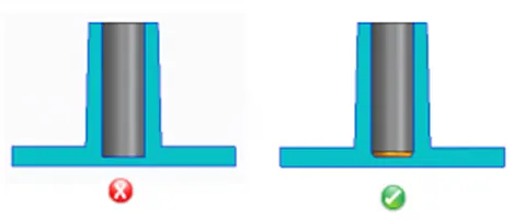
- Minimum Draft for Boss OD
An appropriate draft on the outer diameter of a boss helps easy ejection from the mold. The draft is required on the walls of a boss to permit easy withdrawal from the mold. The recommended value for the minimum draft on the outer surface of the boss is greater than or equal to 0.5 degrees.
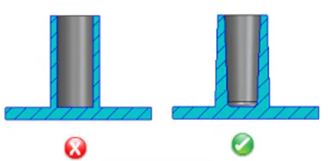
- Minimum Draft for Boss ID
Designs may require a minimum taper on the ID of a boss for proper engagement with a fastener. The draft is required on the walls of a boss to permit easy withdrawal from the mold. It is recommended that minimum draft on the hole in boss should be greater than or equal to 0.25 degree.
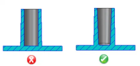
- Boss Height to OD Ratio
A tall boss with the included draft will generate a material mass and thick section at the base. In addition, the core pin will be difficult to cool, can extend the cycle time and affect the cored hole dimensionally. It is recommended that the height of boss should be less than 3 times of outer diameter.
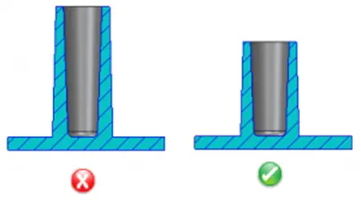
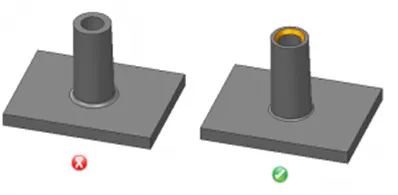
- Minimum Radius at Tip of Boss
Under service conditions, bosses are often subjected to loadings not encountered in other sections of a component. A fillet of certain a minimum radius value should be provided at the tip of a boss to reduce stress.
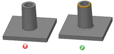
- Chamfer at top of Boss
Boss should have chamfer on top. A chamfer at top of boss is good lead in for the fasteners.
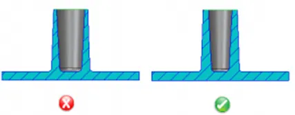
- Wall Thickness of Boss
Wall thicknesses for bosses should be around 60 percent of the nominal wall to minimize sinking. Wall thickness greater than this can create voids and sink marks and may also expand the cycle time.
However, if the boss is not in a visible area, then the wall thickness can be increased to allow for increased stresses imposed by self-tapping screws.
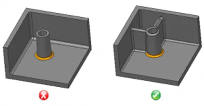
- Standalone Boss
Bosses and other thick sections should be cored. It is good practice to attach the boss to the sidewall. In this case, the material flow is uniform and provides additional load distribution for the part. For better rigidity and material flow, a boss should be connected to the nearest side wall.
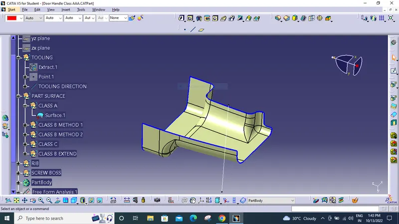
FOR CLASS A SURFACE CHECKING WHICH IS THEBEST DIRECTION FROM WHERE ONE CAN SEE MAXIMUM EDGES FROM THE NORMAL VIEW .
THEN EXTRACT THAT SURFACE CREATE A POINT AND CREATE A LINE FREM THAT.
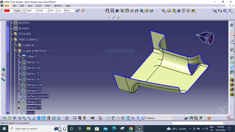
FOR CLASS B SURFACE USE THE OFFSET COMMAND. THE OFFSET IS DONE AT 2.5MM
SOME PATACHES CAN BE SEEN THIS PATCHES CAN BE REMOVED BY
WHEN WE HAVE 2 DIFFERENT SURFACE SO FOR THAT I HAD EXTRACTED THE BOUNDRY AND THEN TRIM TO REQUIRED PORTION.
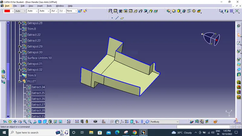
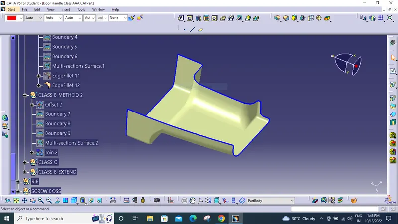
THE ABOVE FIGURE OF CLASS B SURFACE IS MADE WITH EXTRACT AND EXTROPOLATING METHOD WE CAN SEE THE SUFCACE FINISH IS VERY GOOD NO SHARP EDGE IS THERE.
BUT THIS METHOD IS VERY LONG .
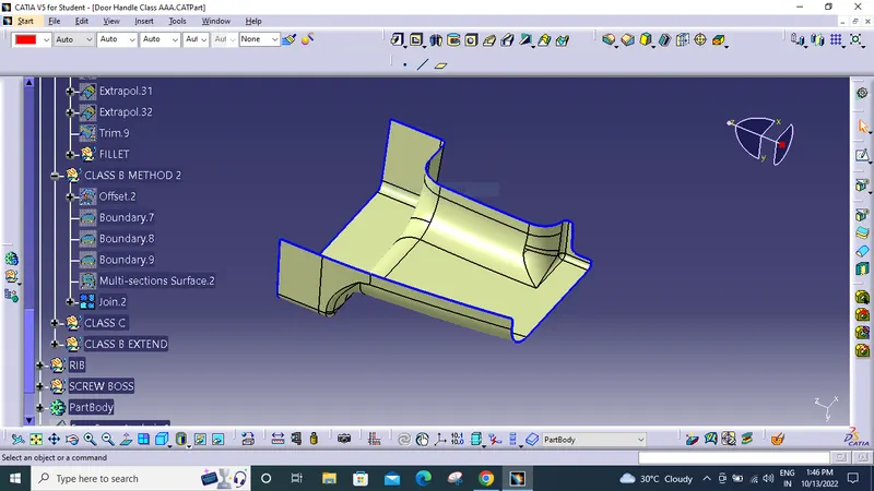
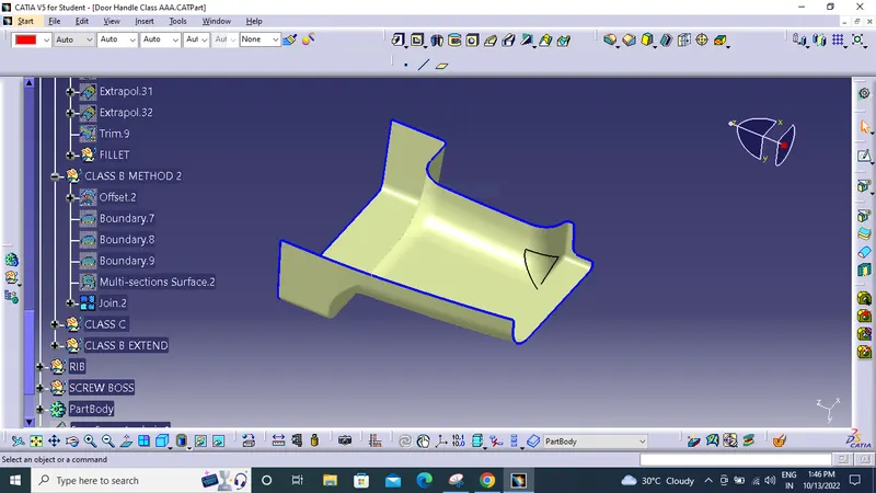
THIS CLASS B SURFACE IS CREATED WITH MULLTISECTION METHOD WE CAN SEE THE SURFACE FINISH IS NOT VERY GOOD MEANS HAVING SHARP EDGE.
BUT THIS METHOD IS VERY SHORT AND TIME CONSUMING.
I TOOK THE CLASS B USING MULTISECTION BECAUSE I COMPLEATED IT FIRST AND THEN NOTICED.
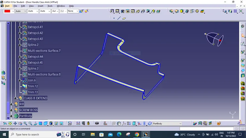
THIS IS THE CLASS C SURFACE WHICH IS SWEEP FROM THE CLASS A SURFACE WITH THE TOOLING DIRECTION SOME PLACES USED WITH RESPECTIVE TO SURFACE ALSO.
{ BOUNDRY- SMOOTCURVE-SWEEP}.
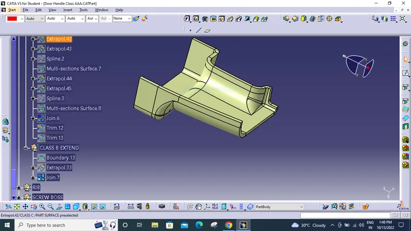
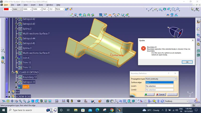
THIS IS HOW CLASS A AND CLASS C SURFACE LOOK WHEN JOIN.
TO CHECK WETHER THIS SURFACE IS FULLY JOIN USE BOUNDRY COMAND WHEN IT SHOWS THIS MESSAGE MEANS IT IS CLOSED SURFACE.
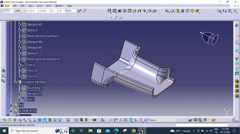
FINAL BODY
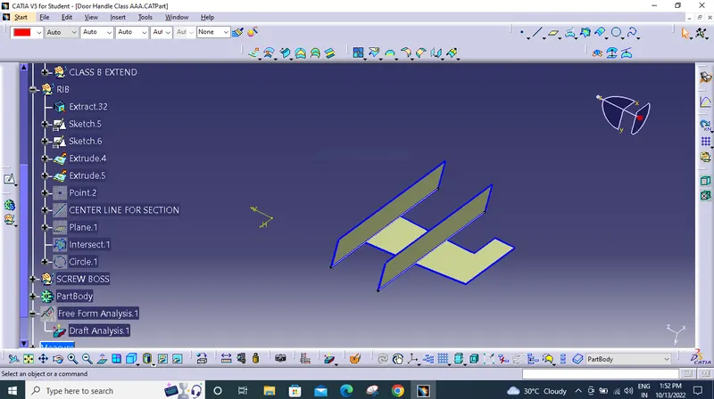
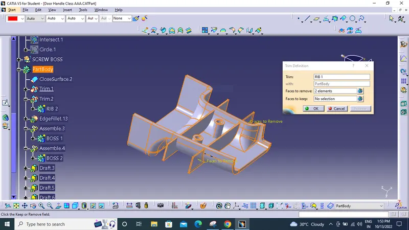
FOR RIB EXTRACT TJE SURFACE CREATE PROFILE EXTRUDE AND THEN THICKEN IT
THEN USED UNITRIM TO REMOVE UNWANTED PARTS.
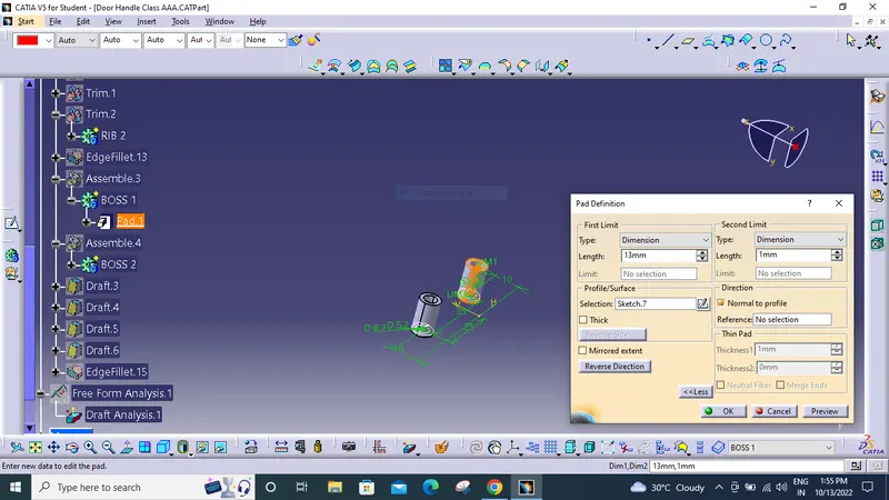
FOR BOSSS CREATE THE PROFILE AND THEN PAD OPTION IS USED BOTH SIDE AND THEN ASSEMBLED IT IN THE MAIN BODY.
DRAFT ANALYSIS
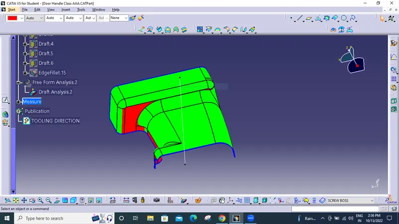
THE FIRST DRAFT ANALYS IS IS DONE ONT THE CLASS A SURFACE TO SEE WETHER THE TOOKING AXIS IS CORRECT OR NOT HERE IT IS SHOWING GREEN COLOR AT THE MAXIMUM PART WHICH MEANS THE DRAFT ANGLE IS 3 OR MORE THAN 3 DEGREE. THIS MEANS THE TOOLING AXIS IS CORRECT.
THE RED ARE SHOWS THE DRAFT ANGLE IS LESS THEN 3.
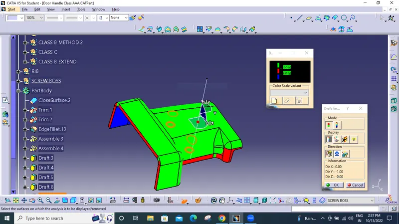
HERE THE SECOND DRAFT ANALYSIS ID DONE ON THE SOLID BODY HERE IT IS SHOWING GREEN COLOR WHICH MEANS THE DRAFT ANGLE IS 3 OR MORE THAN 3 DEGREE.
THE BLUE COLOR MEANS THE DRAFT ANGLE IS NEGATIVE DEGEE WHICH IS MANDATORY FOR THE SOLID BODY BASE SIDE.
THERE ARE SOME RED PORTION WHICH IS ON A SURFACE THE A WHICH WILL COME AT SOME PORTION.
RED LINES ARE OF FILLETS WHICH IS ACCEPTABLE.
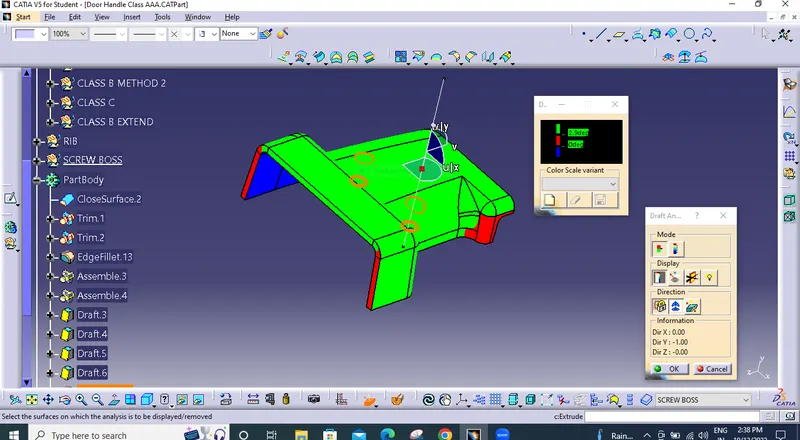
WHEN THE DRAFT ANGLE IS 2.9 SOME OF THE ARE GETS GREEN WHICH IS ACCEPTABLE.
THE RED COLOR IS COMING BECAUSE IT IS VERTICAL PORTION.
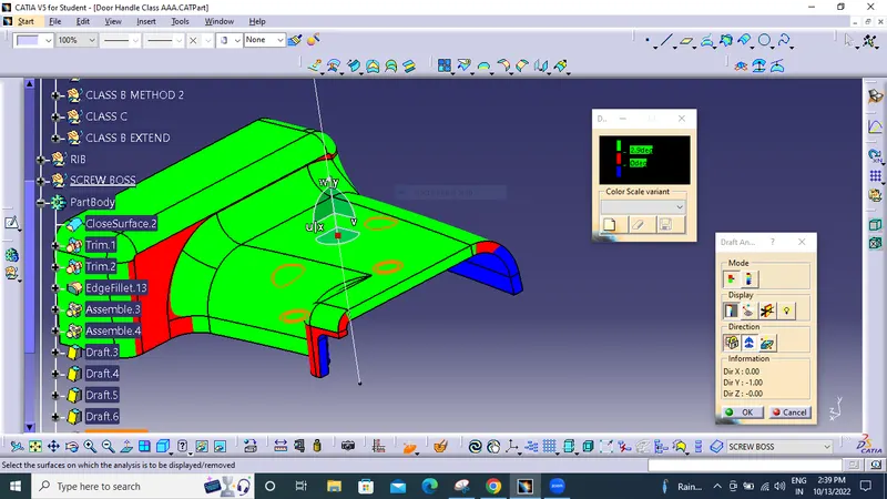
HERE ON THE EDGES THERE IS BLUE COLOR WHICH IS NEGATIVE DRAFT AND IT SHOULD NOT BE THERE . I USED THE SPLINE AND THEN CREATED MULTISECTION AT THE CORNER .
I HAD TRIED TO PROVIDE 100 DEGREE IN SWEEP COMAND WITH RESPECTIVE TO DRAFT ANGLE. WHILE CREATING THE C SURFACE BUT EVEN IT IS COMING BLUE.
DISCUSSED WITH SIR THEY TOLD NO PROBLEM.
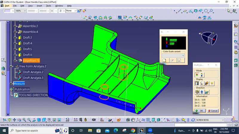
HERE I GAVE 0.45 DRAFT ANGLE FOR THE BOSS AND THE RIB IT IS POSITIVE.
FULLY CUNSTRAIN
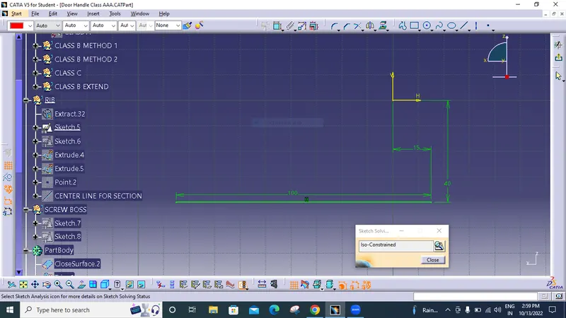
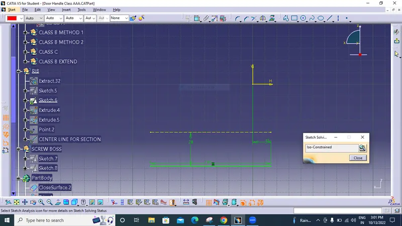
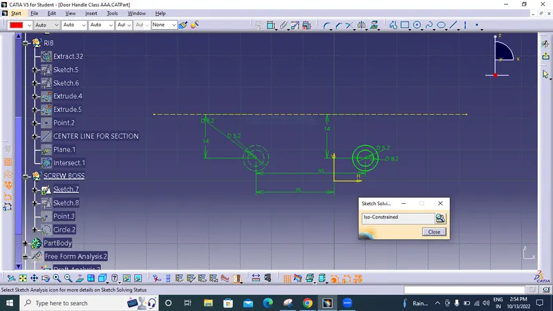
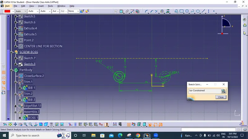
FEATURE TREE.
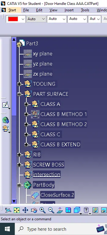
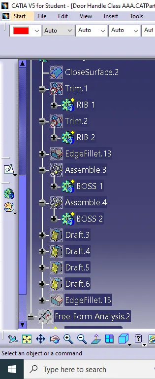
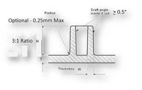
Create the Screw boss for the Drill Handle considering the design rules mentioned in the video.
General Guidelines for Bosses:
- Draft - 0.5 degrees on the walls of boss
- Thickness - Typically 40%* of the nominal wall at the base.
- Height to Diameter Ratio - 3:1
- Radii - 0.25mm maximum radii.
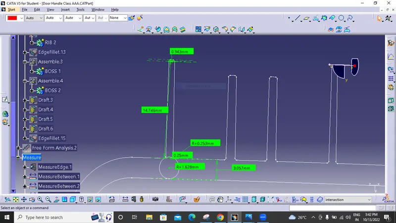
- THICK NESS OF THE COMPONENT IS TAKEN AS 3 MM
THANK YOU