Week 9 - Attachment Feature Creation (Ribs & Screw Boss) - Challenge 1
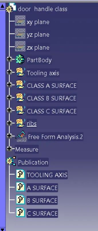
TOOLING AXIS :
- Extract surface from the a surface
- create a point on the extracted surface using point option
- using the line option create a line in xy direction make it as main tooling axis
CLASS A SURFACE
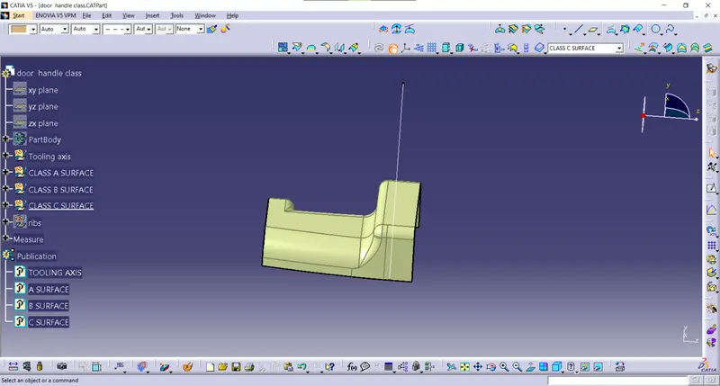
DRAFT ANALYSIS PERFORMED ON CLASS A SURFACE
CLASS B SURFACE
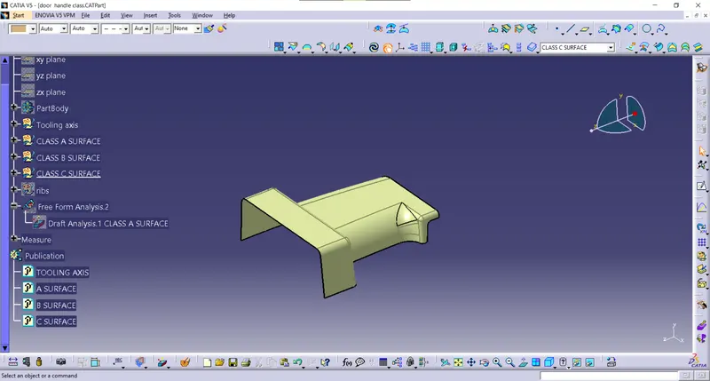
CLASS C SURFACE
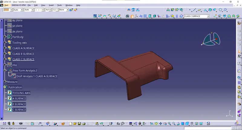
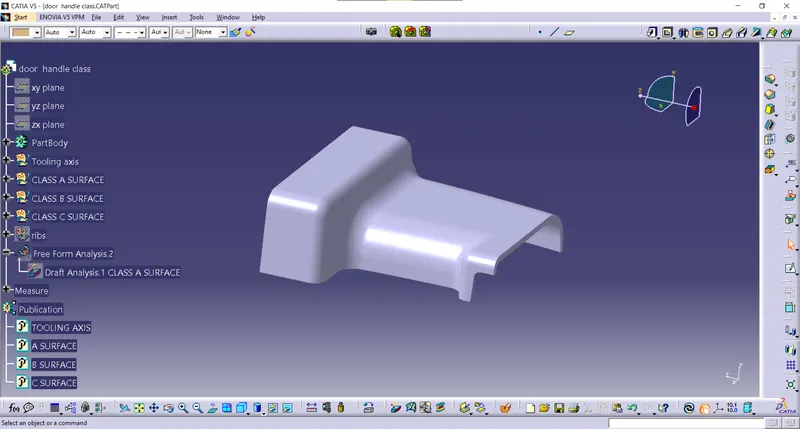
SOLID SURFACE
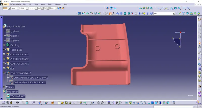
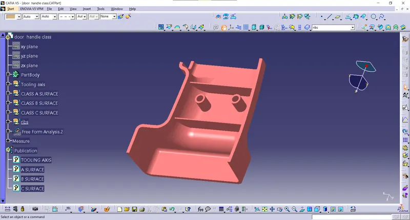
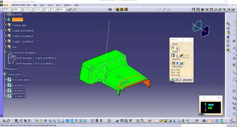
DRAFT ANALYSIS FOR SOLID SURFACE
draft analysis
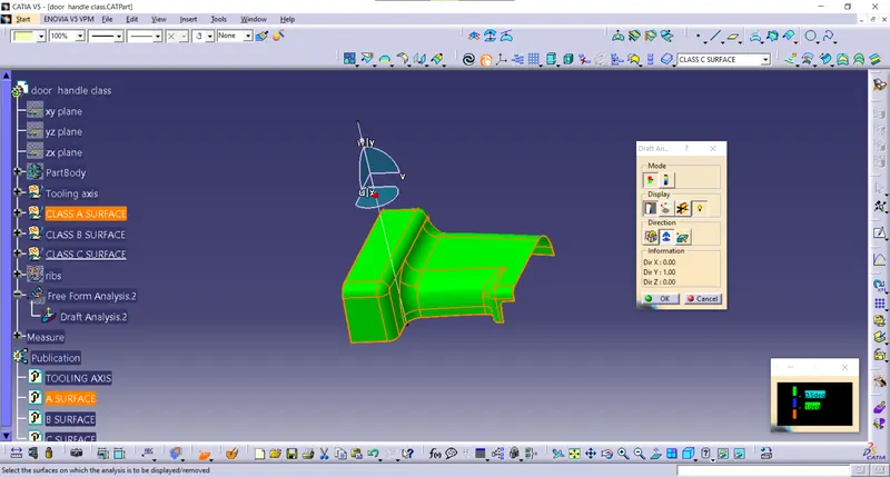
- nominal draft angle is 3 deg. but for this component some part are not passing the 3 deg draft angle
- so we reduce the draft angle into 0.5 deg for this surface you see this in colour scale
- using feature draft analysis option
- At the first position, the compass on the tooling axis of the component then lock the compass and click on the component where x appears of that color of the component changes
- the color indicates the various conditions of the draft angle and green where parts are accepted and further processed
- by using analysis on the running point icon various surface position is seen
- 0.5 deg which satisfies the surface which can be seen in green color
INTERSECTION