Week 9 - Attachment Feature Creation (Ribs & Screw Boss) - Challenge 1
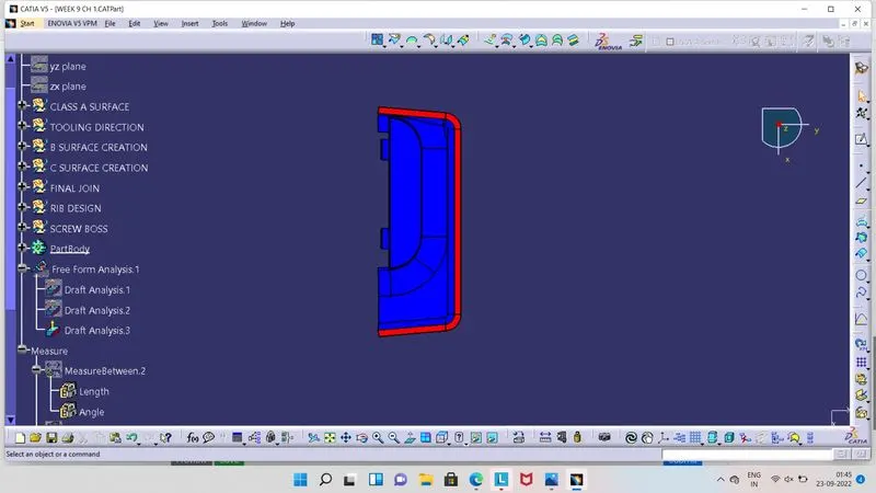
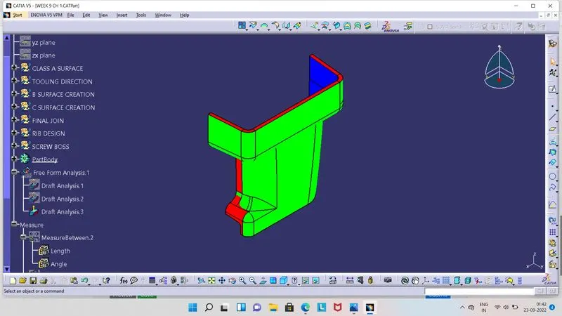
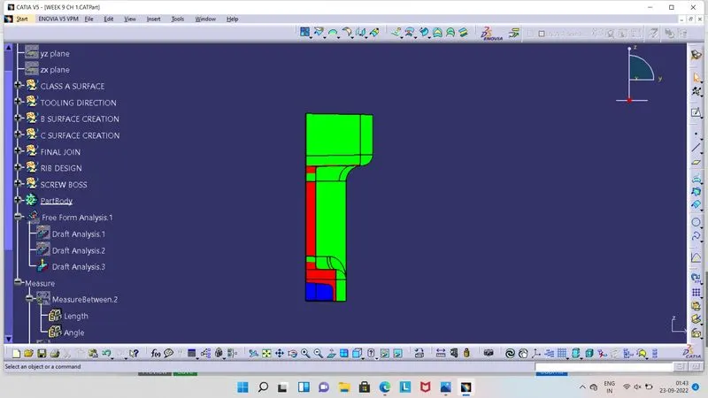
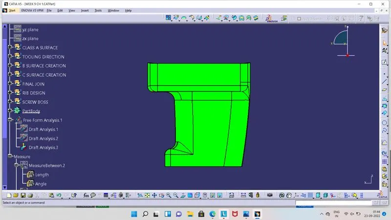
- Screenshots of Draft Analysis reort of the given Class A Surface.
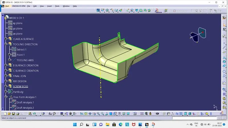
- For a Draft Analysis, we need Tooling Axis, so here, we exract flat surface from Class A Surface and create center point there.
- Now take a line normal to the surface through point. This line is our Tooling Axis.
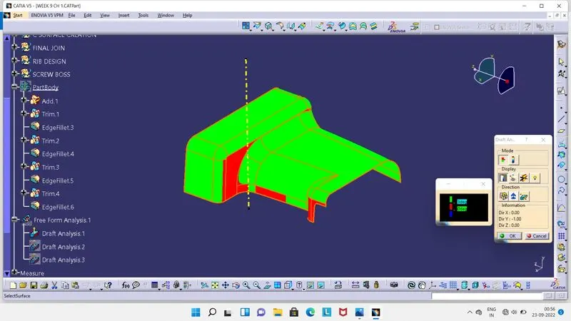
- Onc we get the Tooling Axis, we can go for Draft Analysis, so click on Feature Draft Analysis tool.
- We have to Ensure that, component should in matrial view mode.
- As shown in above image at right side of the screen, two boxes are there. From there click on Compass, so Compass will be seen at secrren.
- Now align this Compass with Tooling Axis and then click on lock symbol and ten on Class A Surface.
- So now Class A Surface get colour on it.
- Green colour indicates that, draft angle is above 3 degrees.
- Red colour indicates that, draft angle is between 0 to 3 degrees.
- Blue colour indicates that. drfat angle is below 0 degrees or negative.
- Draft Analysis Report for the Final Plastic Component.
- Class B Surface :
- Its offset surface of Class A Surface.
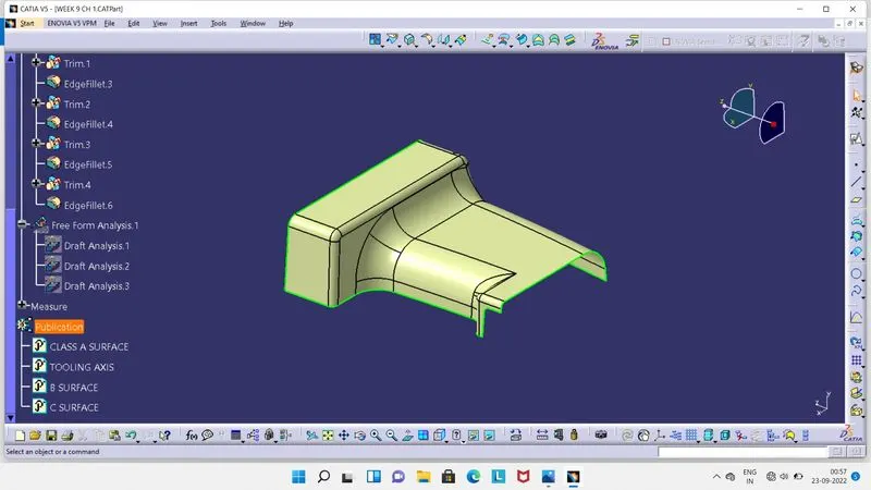
- Class C Surface :
- Its a joining surface of Class A and B Surfaces.
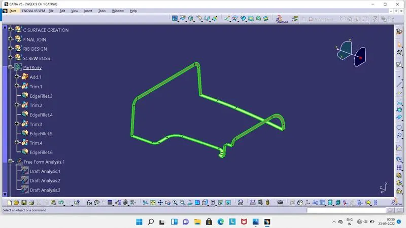
- Joinining Surfaces of Class A, B and C.
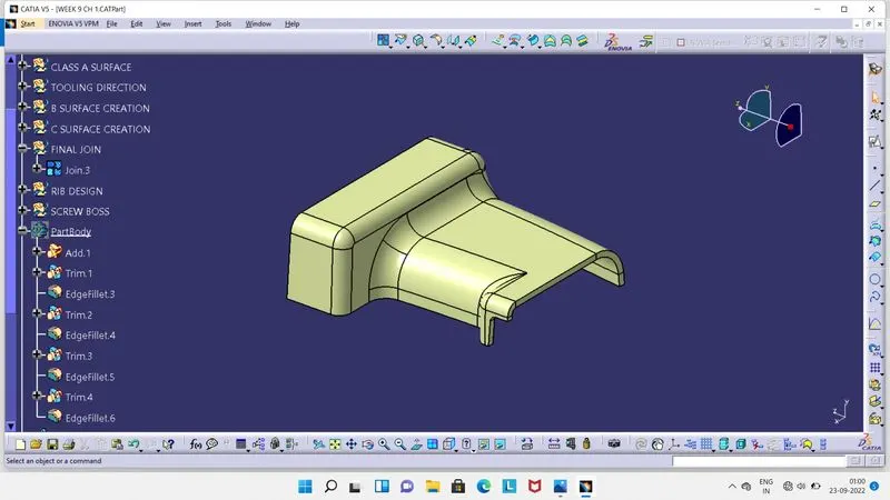
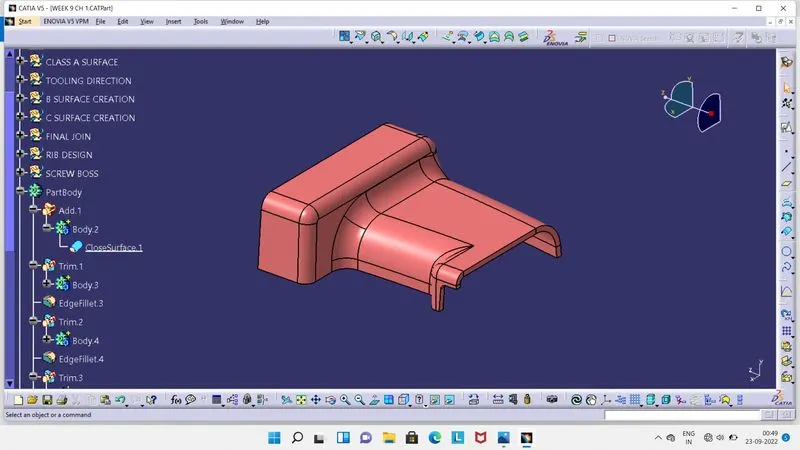
- Final Plastic Component :
- Draft Analysis of the Final Plastic Component without Ribs and Screw Boss .
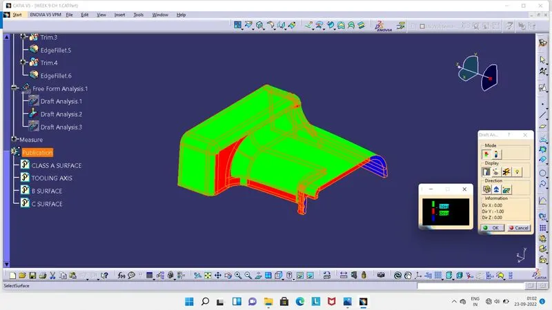
- Click on Feature Draft Analysis tool.
- We have to Ensure that, component should in matrial view mode.
- As shown in above image at right side of the screen, two boxes are there. From there click on Compass, so Compass will be seen at secrren.
- Now align this Compass with Tooling Axis and then click on lock symbol and then on Final Plastic component.
- So now Class A Surface get colour on it.
- Green colour indicates that, draft angle is above 3 degrees.
- Red colour indicates that, draft angle is between 0 to 3 degrees.
- Blue colour indicates that. drfat angle is below 0 degrees or negative.
- Rib Design :
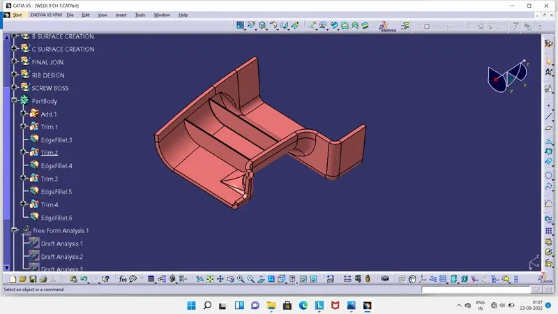
- Ribs are provided to the component for support the component in terms of strength.
- So for prevention from plastic defect, we have to use standard values during the designing of Ribs.
- Drfat should be 0.5 degrees per side.
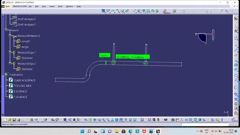
- Base Thickness of the Rib should be 0.4 × thickness of the component. Here 2.5 is the component thickness, so Rib's base thickness is 1mm.
- Height of Rib should be 5 × thickness of the component, so here we get 12.5mm.
- Radius Fillet should be a 0.25 wherever required.
- Top most tip of the rib having thickness should more than 0.75mm, here we get 0.788mm.
- Here we get Rib Root thickness is 2.68mm.
- Intersection and Rib Root thickness :
- Screw Boss :
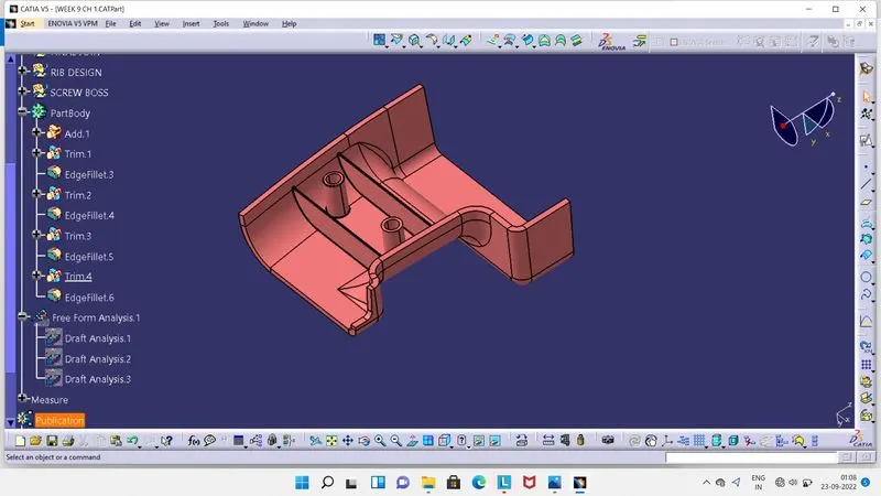
- For aseembly and fastening the components Screw Boss are created.
- Here we have taken 5.2mm as a Diameter for hole of screw boss.
- As wall thickness is equal to 0.6 × component thickness, so we get 1.5mm per side, so our outer circle is with 8.2mm diameter.
- The ratio of Height and Diametet should be 3:1, so by this relation we get Height here is, 15.6 mm.
- Drfat should be a 0.5 degrees per side.
- Radius fillet should be a 0.25 mm wherever required.
- Draft Analysis of Final Component :
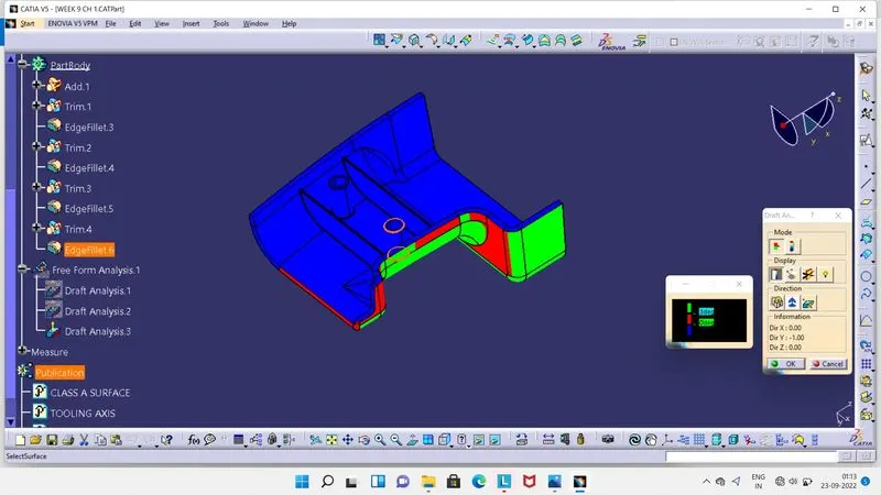
- Click on Feature Draft Analysis tool.
- We have to Ensure that, component should in matrial view mode.
- As shown in above image at right side of the screen, two boxes are there. From there click on Compass, so Compass will be seen at secrren.
- Now align this Compass with Tooling Axis and then click on lock symbol and then on Final Plastic component.
- So now Class A Surface get colour on it.
- Green colour indicates that, draft angle is above 3 degrees.
- Red colour indicates that, draft angle is between 0 to 3 degrees.
- Blue colour indicates that. drfat angle is below 0 degrees or negative.
- Screenshots of the completed design in various orientations.
- Isometric View :
- Front View :
- Side View :
- Top View :