Week 9 - Attachment Feature Creation (Ribs & Screw Boss) - Challenge 1
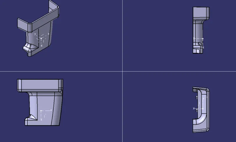
Draft analysis and Feature Attachment creation of Door Hndle
AIM:
- To Create the solid component from the given Class-A surface of Door Handle.
- To Create the tooling axis for the given Class-A Surface meeting the requirements of the draft angle.
- To perform the Draft analysis on the model.
- To create a rib and screw boss attachement to the door handle component.
Procedure:
1. TOOLING AXIS CREATING:
The Tooling Direction is basically the direction that the mold pulls a part. The mold is built in two separate pieces, basically. You have a Cavity side and you have the Core side. The Core pulls apart from the Cavity and that's the Dye line or the Tooling Direction.
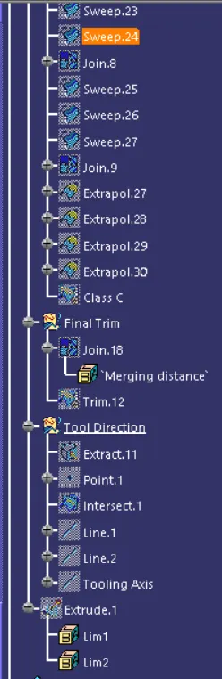
By analysing the component the most easily ejectable direction is somewhere close to the Z direction, so we have made a sketch on the XY plane of Axis System to create a bisecting line considering the 2 faces which might be difficult to be tooled.
First the a surface is extracted anf a point and axis system is created.
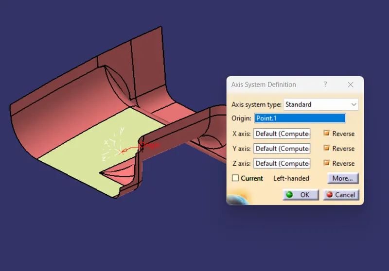
Next a intection boundary along the xy plane of the axis system is created. Accordinly the two outer lines and created and a common bisecting line is created as a Tooling axis.
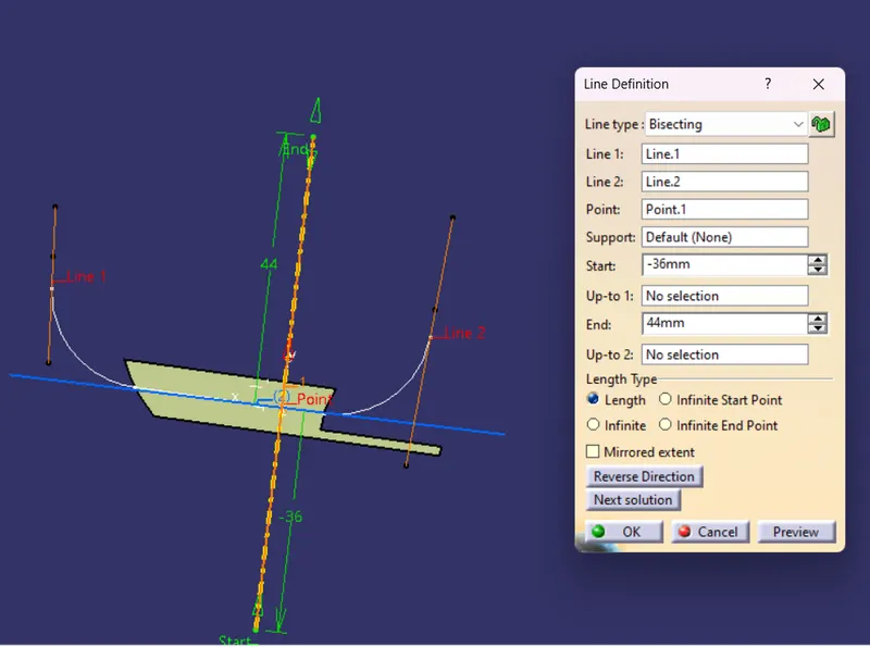
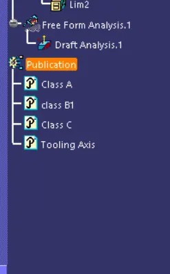
Since the Tooling axis is created next is to publish it and create class B surface.
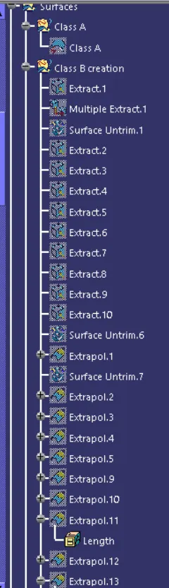
- Class B cration:
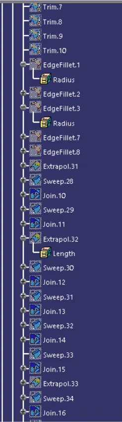
First thing we have to do is to extract the base surface using extract tool  and multiple extract one by one carefully.
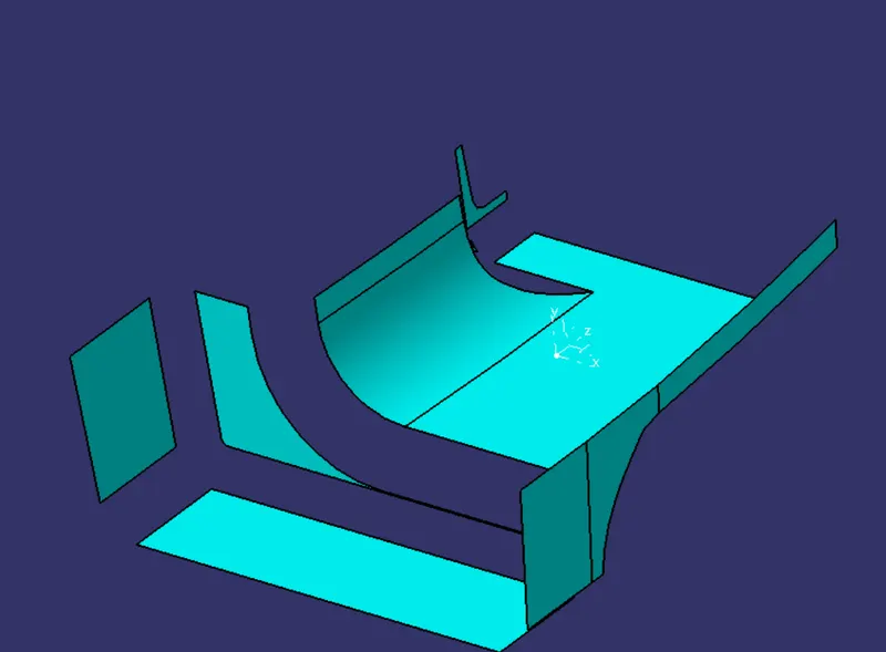
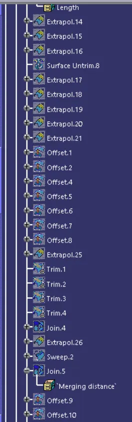
Untrim the surface and extrapolate the walll surface. Trim the wall surfaces as required.
Similarly follow the procedure for all the surfaces and trim them all together.
Offset the trimmed surface by 2.5mm thickness towards outside.
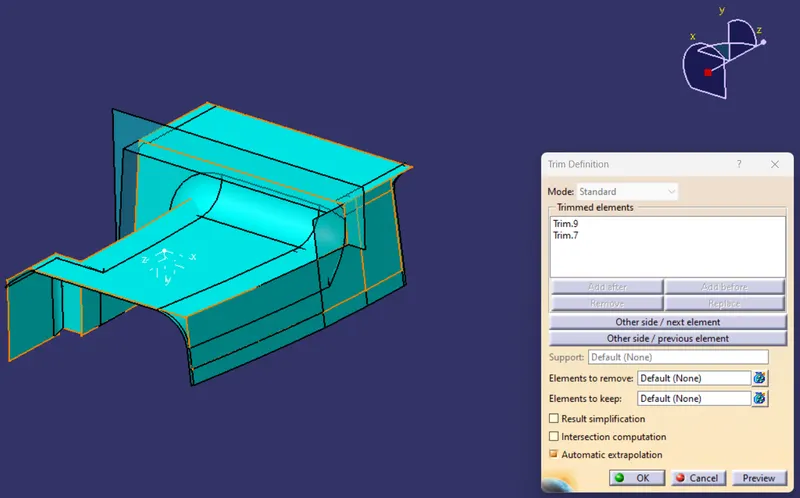

Apply the edges fillet to the edges and check for the fiilet dimension by measuring on the class A surface.
Publish the Class B surface.
- Class C creation:
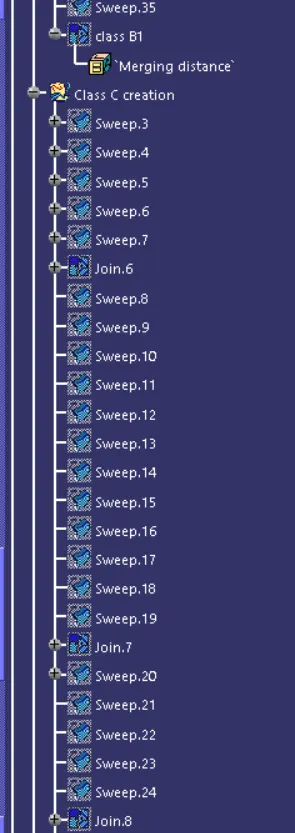
Create the boundary of the class A first.
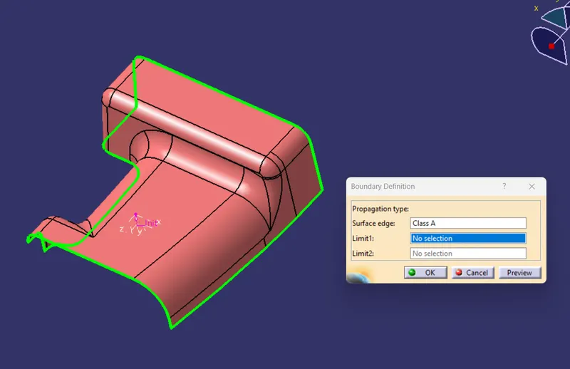
Now select sweep option and and sweep the boundary along the tool axis as draft direction and at an angle 3 degrees.
One by one follow the procedure for all the egdes.
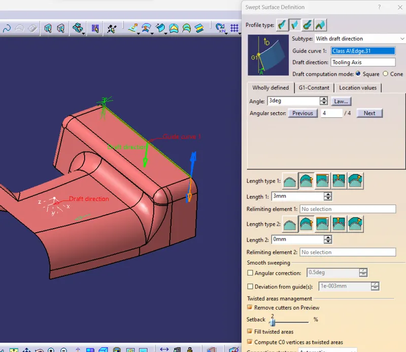
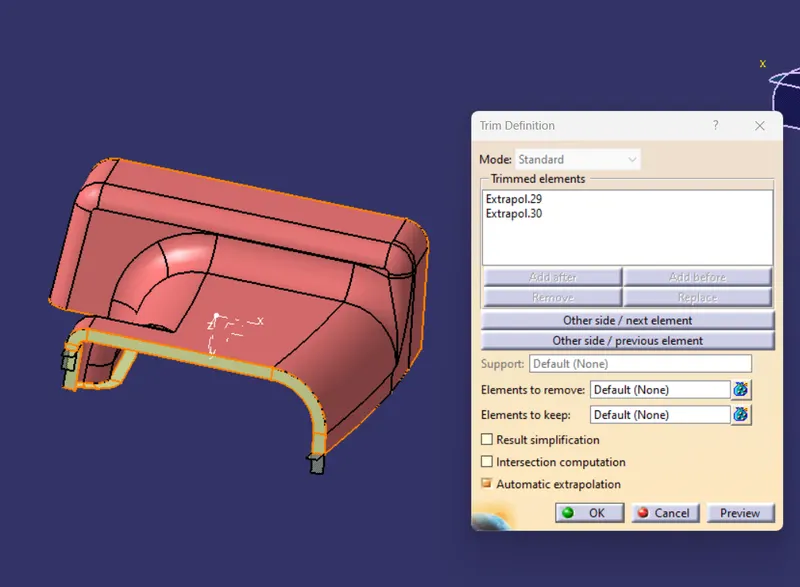
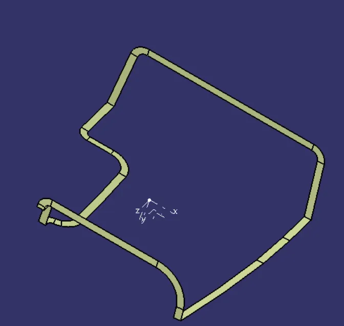
Once all sweep operation is done, Join all of them and the class C surface is created.
- Creating Solid Body:
Join the class surface with class A first. Extrapolate the surfaces as required to carry trim operation.
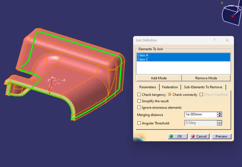
Now trim the joined suraface with the class B surface.
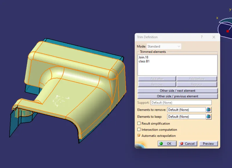
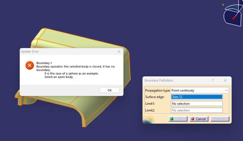
Now open part body workbench and check for the boundary if open before creation of solid body. If there is no open edges, click close surafce option and click the body to be converted to solid.
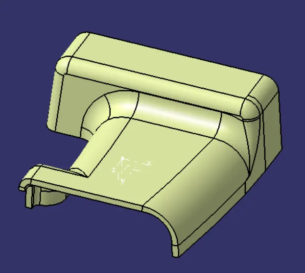
Steps for Draft Analysis:
Change the view mode to the custom view and select view paramater as Material mode, then the draft analysis is enalbles.
Click the draft analysis option  , move the compass with the red dot to align with the tool axis.
Now lock the compass and click anywhere on the part, the color will be changed.
The green color shows that the surface satisfies the draft angle and other color if the angle is not satisfied. This can be corrected by altering the angle and measuring at points to get succesfully draft to get satisfied.
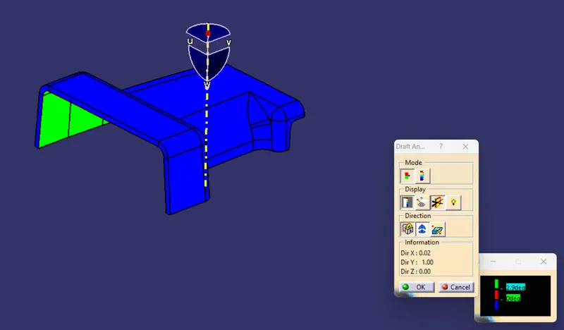
- Rib Creation:
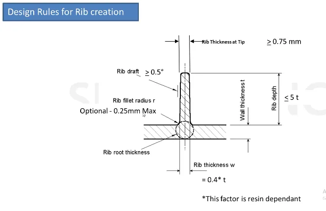
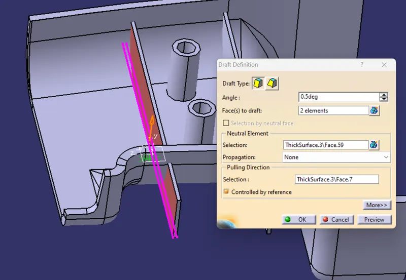
Ribs are thin wall protrusions that extend perpendicularly from a wall or plane. They are usually found in clusters offering support to a plane that would have otherwise been too thick, but can also be stand-alone support for a single wall. They are commonly used to provide additional support and strength to a part. Thickness and location are essential to rib design.
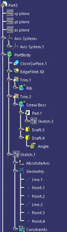
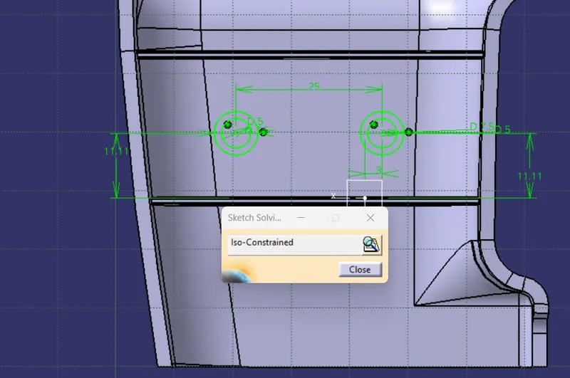
First, the base surface where the rib has to be created is extracted using the Extract command. A positioned sketch is created and the profile for the rib is drawn.
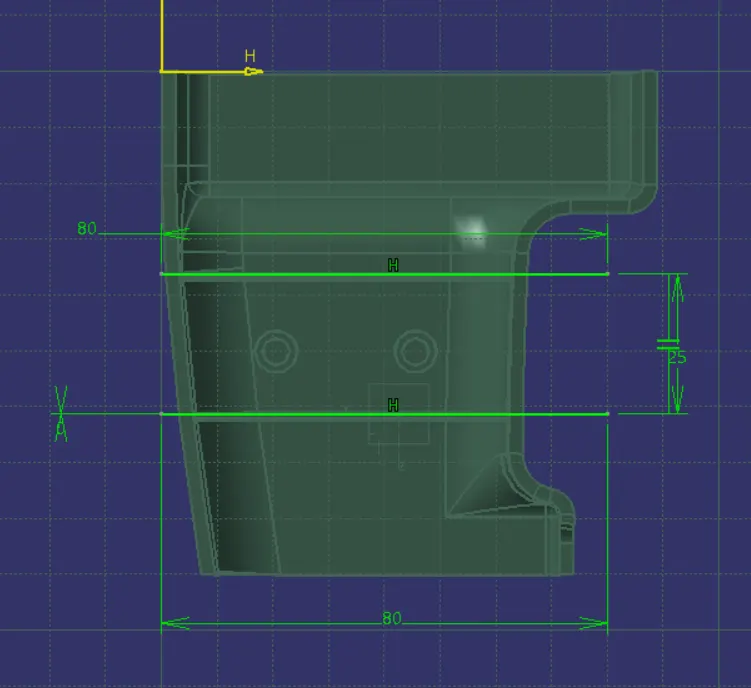
Select Sketch Analysis icon for more details on Sketch Solving Status
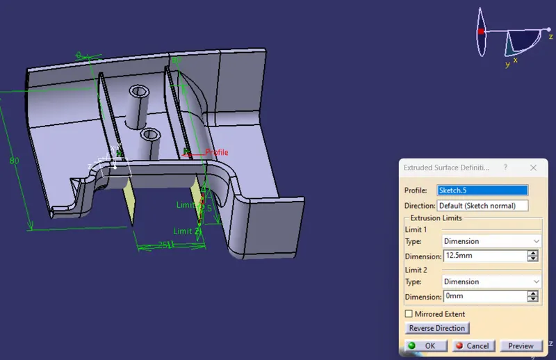
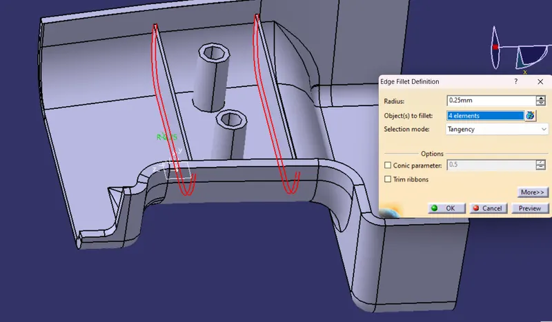
The filled is applied to the edges of the rib of 0.25mm.
Now, we have to check for the Rib root thickness. To check for the Rib root thickness, We have to take an Intersection with the XY plane and the Coin holder component. Once we get to the intersection we have to create a tri-tangent circle at the rib area and measure it. The value must be within 30% greater of the wall thickness.
- Screw Boss Creation
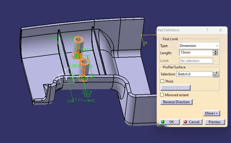
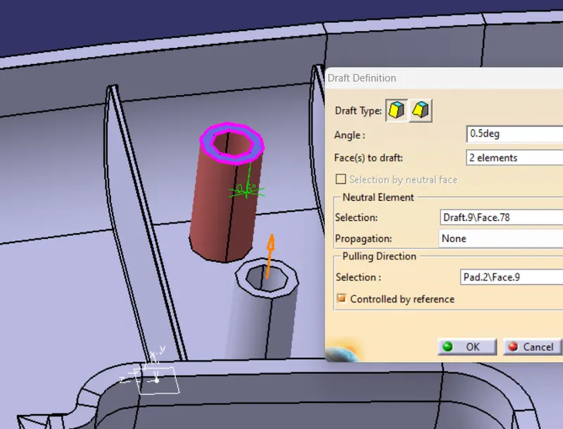
Screw Boss features are commonly found in injection molding designs. They are used to aid in the assembly of molded parts by providing a channel for a screw. Their primary use is to strengthen holes or slots in the surface present in the part model.
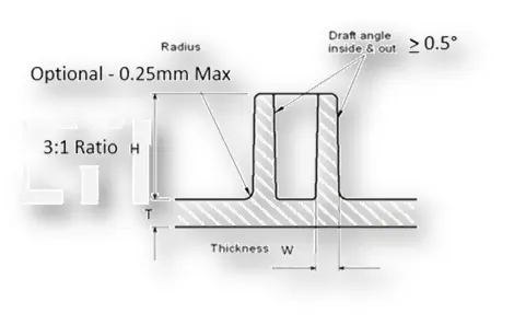
General Guidelines for Bosses:
- Draft - 0.5 degrees on the walls of boss
- Thickness - Typically 40%* of the nominal wall at the base.
- Height to Diameter Ratio - 3:1
- Radii - 0.25mm maximum radii.
Different Views & Expanded Feature Tree: