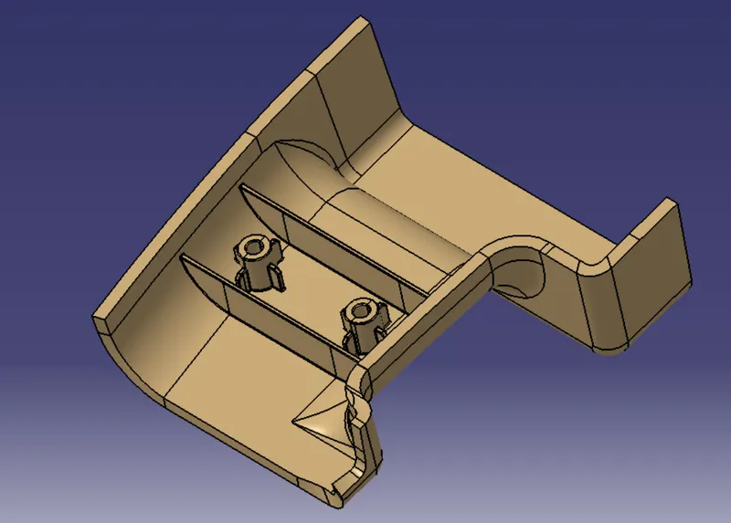
Week 9 - Attachment Feature Creation (Ribs & Screw Boss) - Challenge 1
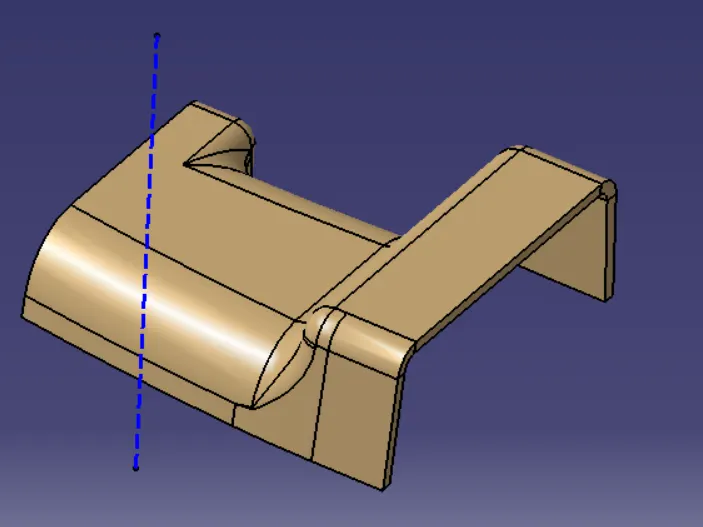
Tooling Axis
It is defined to make sure that all the surfaces maintained a minimum draft angle with drafting direction so that the process can be smoothly carried out.
- A point is made along the flat surface and a new axis system is created.
- A dummy tooling axis is made based on the visual inspection
- The model then intersected with multiple planes to make intersection sketches.
- The sketches are inspected and lines are created along the direction with minimum draft angles, these lines are bisected to give the final draft angle.
Rib Calculation
Determining height with height-to-width ratio.
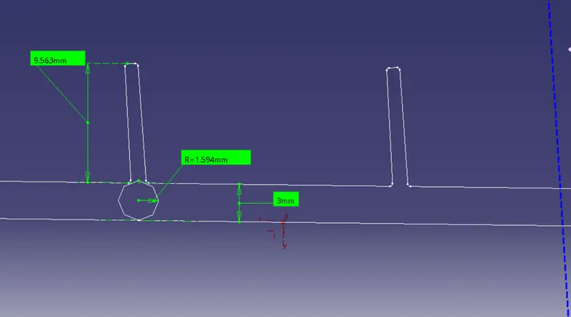
The maximum width of the rib is: 1.2 mm
The minimum width of the rib is: 1.06 mm
The minimum Draft Angle is:0.5 deg
The final Height of the Rib is: 9.56 mm
The final rib root diameter is: 3.188 mm
Height to diameter ratio is: 3:1
The thickness of the model is: 3mm
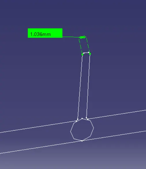
Boss Analysis
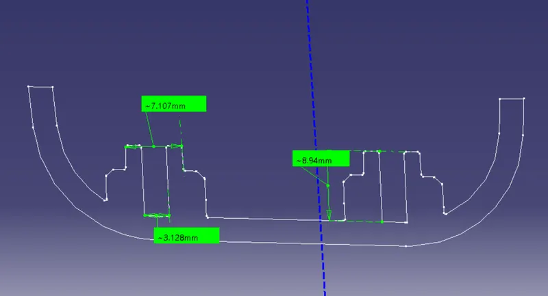
Heignt to diameater ratio is : 3:1
The boss diameter is : 3mm
Height of the boss screw is : 9mm
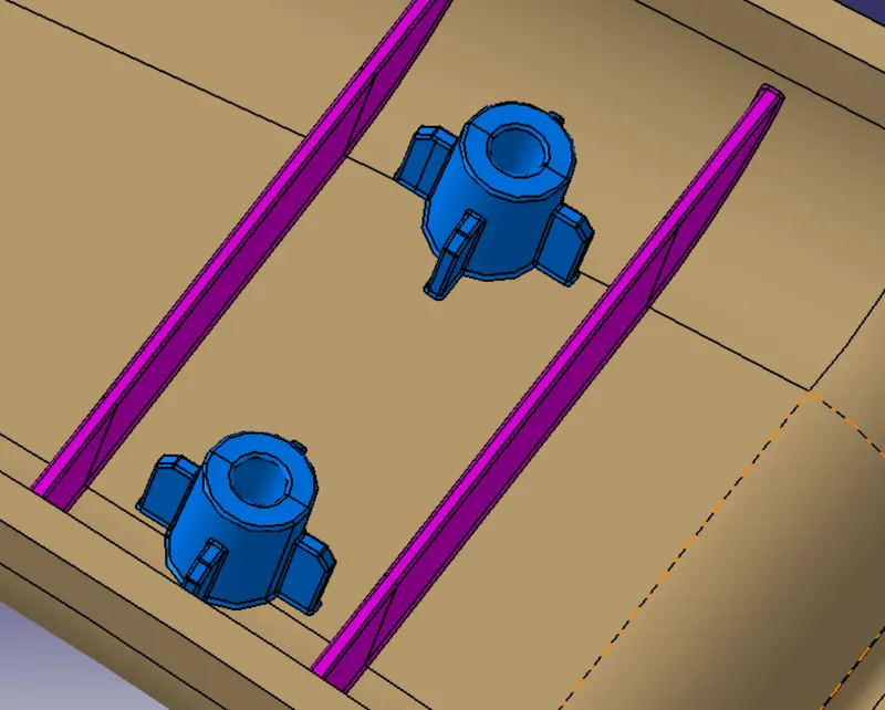
RIB & Boss Screw
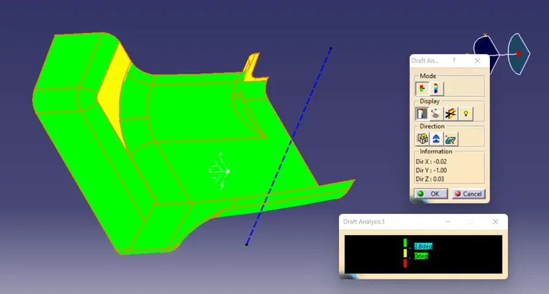
Draft Analysis
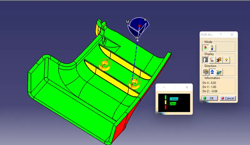
The draft analysis is conducted to make sure that every surface has a minimum draft angle with the tooling direction.
- The draft direction is selected and the view is changed to material mode.
- The surface to be drafted is selected, and all the draft angles are visually analyzed with the help of color code. If there is any problem the draft direction is tilted or moved accordingly.
Class A Surface
Solid Model With Ribes
Standard Views
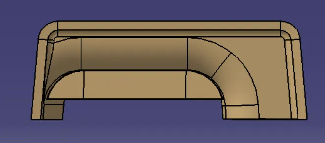
Front View
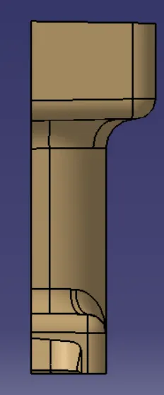
Side View
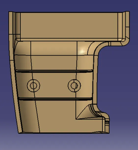
Top View
Isometric View