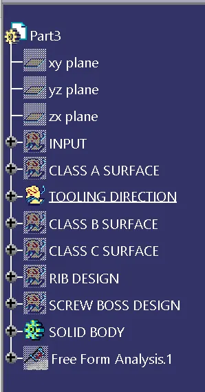
Week 9 - Attachment Feature Creation (Ribs & Screw Boss) - Challenge 1
ATTACHMENT FEATURE CREATION (RIBS AND SCREW BOSS)
AIM: the main aim of this project is to create attachment features like ribs and screw boss.
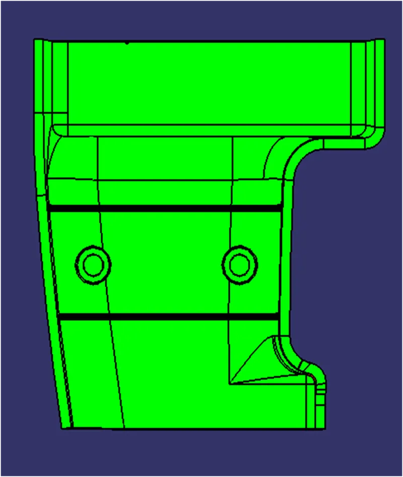
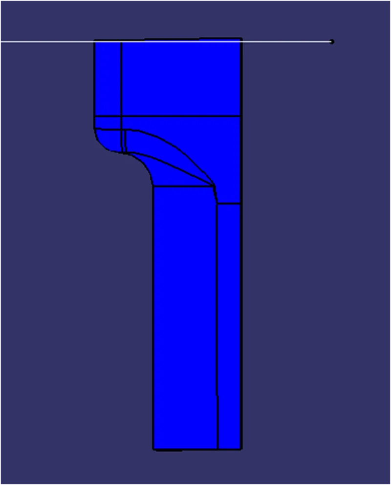
DRAFT ANALYSIS: to start the design first we have to make draft analysis in particular tooling direction. Draft is very important for some moulds. Draft is given to avoid shrinkage, and damage while ejecting the component from the mould.
Generally for plastic materials draft value is vary from 0.5 to 3 degree.
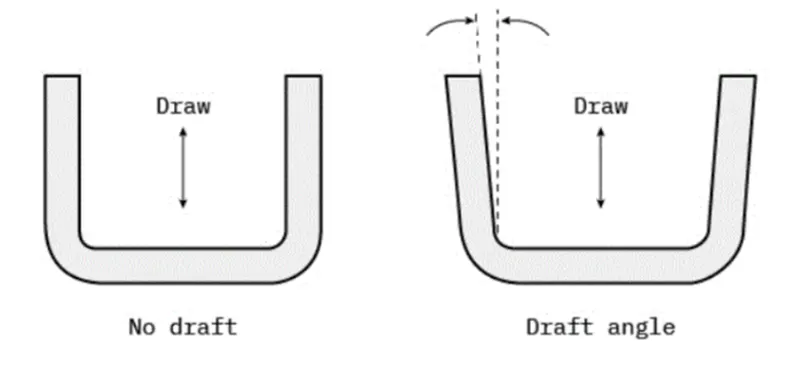
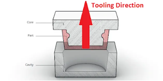
TOOLING DIRECTION:
Tooling direction is basically the direction that the mould pulls a part. The mold is built in two separate pieces, basically. You have a cavity and core side. The core side pulls a part from cavity side and that’s the dyeline or tooling direction and the axis which represents the tooling direction is called tooling axis and selection of this is axis is a crucial step while performing the draft analysis.
CLASS A SURFACE:
In automotive sector class A surface is any of a set of freeform surfaces of high efficiency and quality. Class A surfaces are outer surface which are visible to customer. So this is mainly called styling surface. Class A surfacing is done using CAD applications. Class A surface modelers are also called digital sculptors in the industry. Industrial designers develop their design styling through the A surface the physical surface the end user can feel, touch, see etc.
CLASS B SURFACE:
Class B surfaces are the secondary surfaces that you can see sometimes, but are less important, such as the inside of your ash tray, etc. These must be smooth and "error-free" as well, but are not held to the standards of class A surface.
CLASS C SURFACE:
Class C surface is the surface which connects the class A and class B surfaces. These class C surfaces are mostly now visible as they are covered by other parts when assembled.
SOLID BODY:
After creating class A, B, C surfaces these three are joined and converted in to solid body using close surface command.
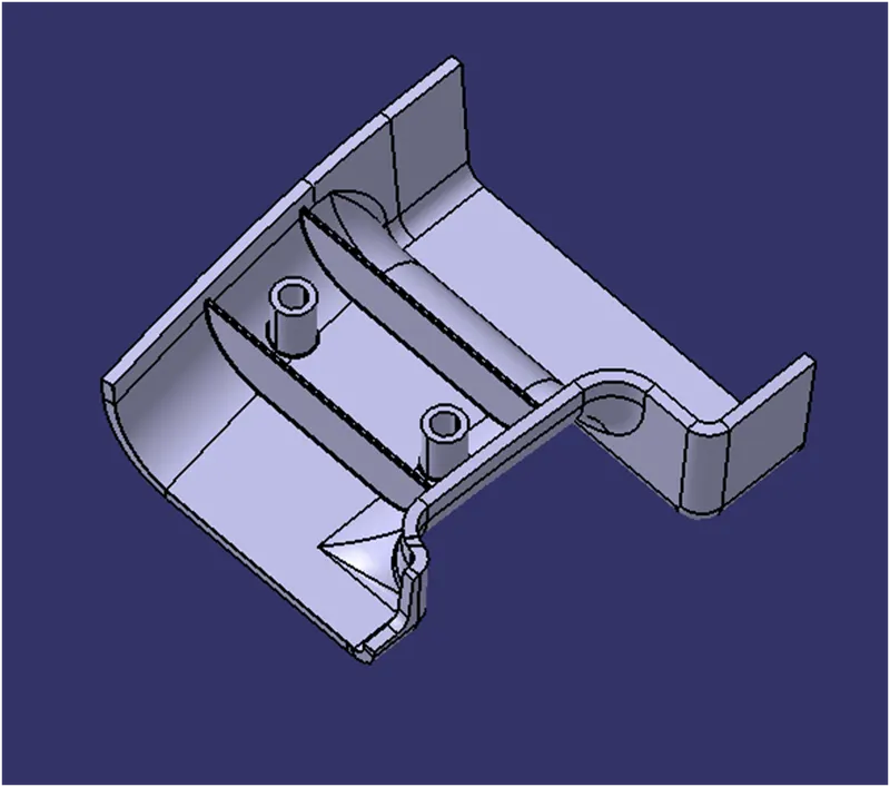
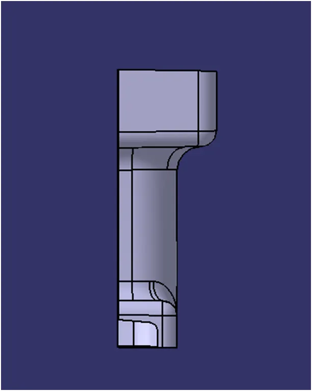
RIB:
Ribs are thin wall protrusions that extend perpendicularly from a wall or plane. They are usually found in clusters offering support to a plane that would have otherwise been too thick, but can also be stand alone support for a single wall. They are commonly used to provide additional support and strength to a part. Thickness and location are essential to rib design.
First the base surface where the rib has to be created using the extract command. A positioned sketch is created and the profile for the rib is drawn.
SCREW BOSS:
Screw Boss features are commonly found in injection molding designs. They are used to aid in the assembly of molded parts by providing a channel for a screw. Their primary use is to strengthen holes or slots in the surface present in the part model.
DRAFT ANALYSIS:
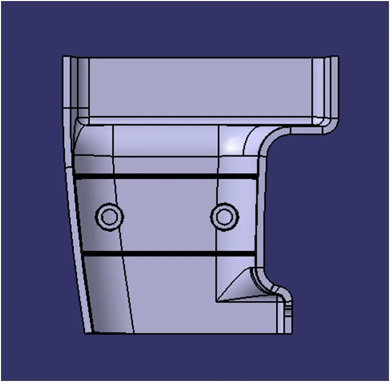
FINAL COMPONENT:
TREE STRUCTURE: