Advanced Sheet Metal Design Using NX Cad Challenge_2_Box Assembly
DESIGN A BOX ASSEMBLY USING NX CAD SHEET METAL APPLICATION
OBJECTIVE:
The aim of the project is to design a box assembly using NX cad sheet metal application.
INTRODUCTION:
Siemens NX is a high end CAD/CAM/CAE software. Siemens NX software is a flexible and powerful integrated solution that helps you deliver better products faster and more efficiently. NX delivers the next generation of design, simulation, and manufacturing solutions that enable companies to realize the value of the digital twin.
DESCRIPTION:
First we have to open the NX CAD sheet metal application and set the sheet metal preferences for commands.
TAB:
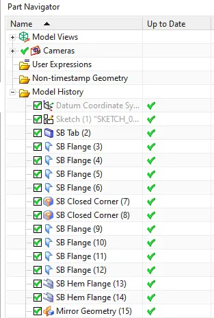
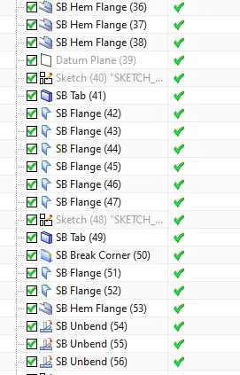
Tab is a basic command which extrudes the sheet metal part using the 2d sketch as reference sketch.
FLANGE:
Flange command creates a bend between two walls and we can adjust angle for bend. And this can be done by selecting the edge and edge should be straight.
CLOSED CORNER:
Closed corner is used to close a corner where two adjacent edges meet by extending the bends and flanges.
HEM FLANGE:
Hem flange is a command used to modify the model by folding the edge of a sheet metal flange over on to itself for the purpose of safe handling or to increase edge stiffness.
MIRROR:
Mirror is used to replicate the body or features with respective to the user defined plane.
UNITE:
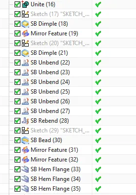
Unite is a command used to combine the volume of two or more bodies in to a single body.
DIMPLE AND BEAD:
Dimple lifts and area of a model inside a sketch that simulates a stamping tool.
Bead lifts material along the contour of a sketch that simulates a stamping tool.
UNBEND:
Unbend is a command used to flattens a bend and the material adjacent to the bend.
NORMAL CUTOUT:
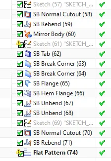
Cuts material by projecting a sketch on to the model and then cutting perpendicular to the faces intersected by the projection.
REBEND:
It restores an unbend feature to its previous bent state along with any features added after the unbend feature.
FLAT PATTERN:
It creates a flat pattern feature from the formed sheet metal part.
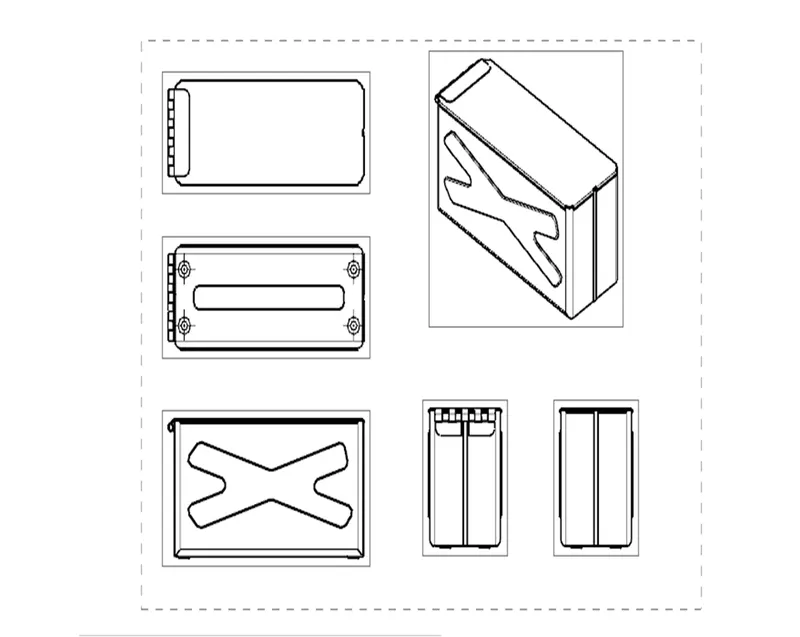
ORIENTATION VIEWS:
ISOMETRIC VIEW
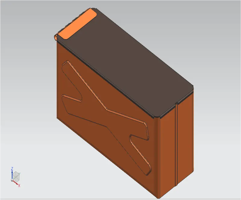
FRONT VIEW
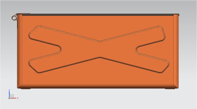
TOP VIEW
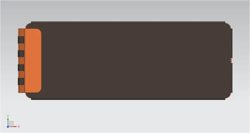
SIDE VIEW
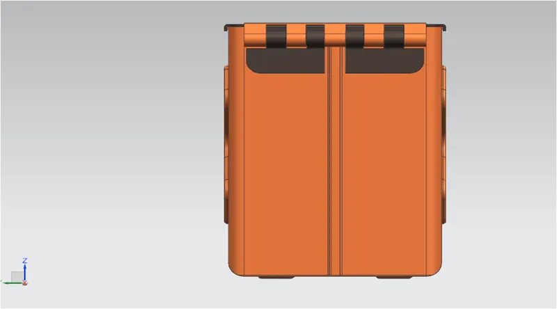
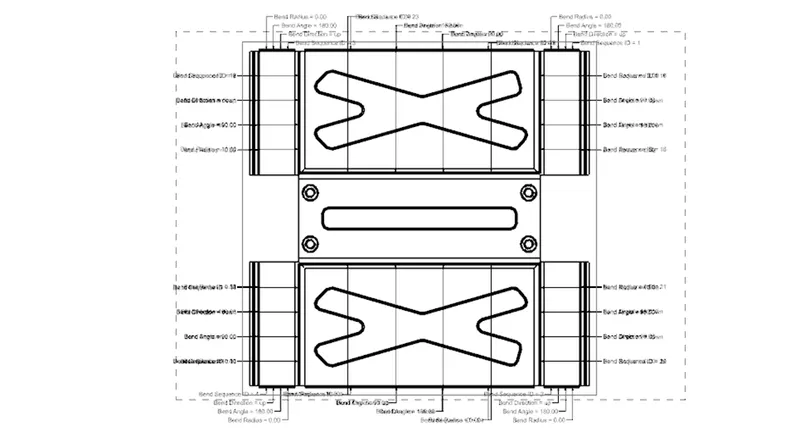
FLAT PATTERN VIEW
DRAFTING:
Starts the drafting application which provides tools to create and maintain drawings of design model.
1.NEW SHEET: Creates a new drawing sheet.
2.BASE VIEW : Creates a model based view on the drawing sheet.
CONCLUSION:
Thus a box is design and drafted by using NX CAD(Sheet metal).
feature manager tree: