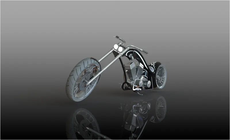
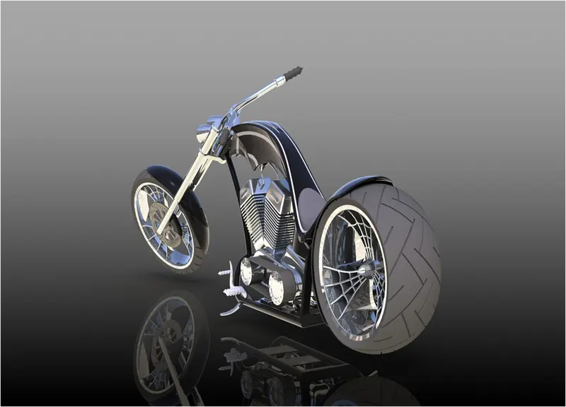
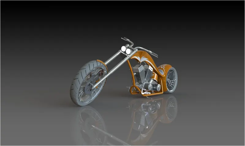
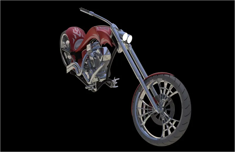
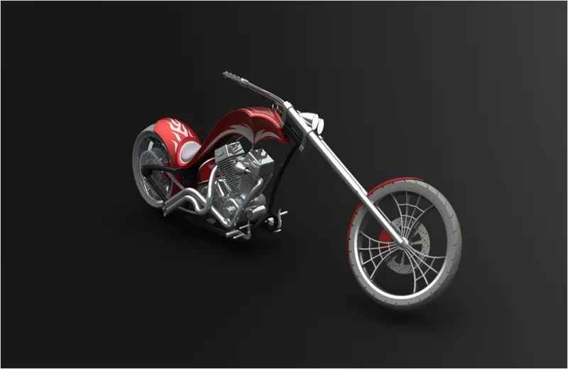
Photo Realistic Rendering
MODELLING OF
AMERICAN CHOPPER
ON SOLIDWORKS
INTRODUCTION:
This project involves the complete details of how to learn
the design of American chopper on SOLIDWORKS.
Here we first learn how to use the commands and next
we draw parts and by using the chopper blueprint sketch
,we get an idea of sketching the parts easily with
dimensions . After designing all the parts we do
assembly of chopper . After assembling all the parts we
add decals , lights , camera and do rendering of chopper
by using SOLIDWORKS visualization.
The components of chopper which we designed are:
1.Chassis
2.Engine
3.Front wheel
4.Rear wheel
5.Front fork
6.Front fender
7.Rear fender
8.Oil tank
9.Kickstand
10.Pedal
11.Gas tank
12.Chain
13.Transmission belt
OBJECTIVE:
- To learn the basic shortcut commands in
SOLIDWORKS. - To know about the features , sketch tools , planes
in SOLIDWORKS. - We can learn how to apply appearances to parts.
- Designing of all the components of American
chopper and assembling those with the help of
SOLIDWORKS - We learn the concepts like decals , lights ,
cameras. - To know about the setting of image quality , and
getting the realistic view of chopper by using
PHOTOVIEW 360. - Rendering of American chopper has done with the
help of SOLIDWORKS visualization.
DESIGN APPROACH:
There are two types of approach in design
procedure .
1. Bottom up approach
2. Top down approach
Bottom up approach: The design approach
in which the most primary operations are
specified first then combined it later to make
larger progressive unit .Here in this project we
have used bottom up approach procedure.
Top down approach: Top down assembly
modelling is an assembly-centric modelling
method where the assembly design is started at
the highest level possible , and individual parts
and subassemblies are defined within the
context of the overall assembly
The features , tools , properties used in the
design of components and the entire model
are:
1.Extrude cut
2.Extrude boss
3.Fillet
4.Chamfer
5.Revolve boss
6. patterns
7.Shell
8.Mirror
9.Reference geometry
10.projected curve
11.knit
12.mate
13.sketch tools
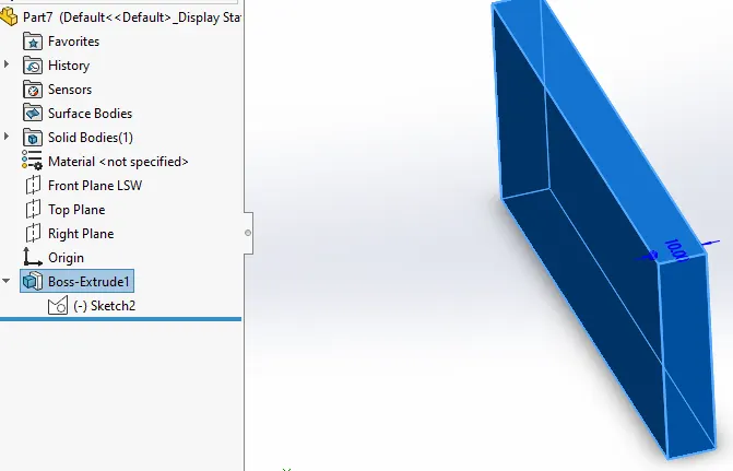
Extrude Boss:
This is a basic feature of SOLIDWORKS. The boss
extrude feature will project a 3D model with the
help of selected 2D sketch . For this first we have to
select a plane ,sketch on it and exit the sketch and
select boss extrude in the feature tab and give
parameters according to our need . Basically boss
extrude extend a sketched profile in one or two
directions as either a thin feature or a solid feature .
Example:
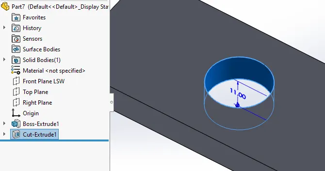
Extrude cut:
As the name includes cut , means it removes the
material from the part . You can create extruded cut
in one or two directions depends on our need by
using the 2d sketch we have drawn . Steps to create
cut extrude are first we have to draw a 2d sketch
using sketch tools and then by exiting the sketch
and going to features tab and selecting extrude cut
and giving parameters we can complete this extrude
cut . Example view of extrude cut is:
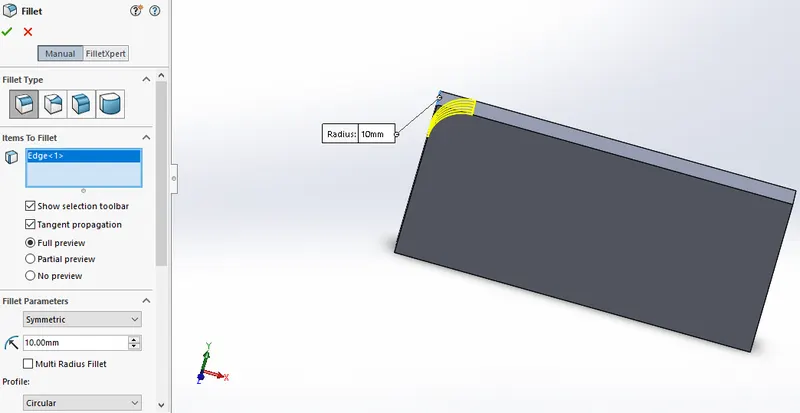
Fillet:
Fillet creates a rounded internal or external face
on the part . You can fillet all edges of a face ,
selected sets of faces , selected edges .on the
feature tab select fillet and then give parameters
like on which edge or face we have to do fillet all
then say ok to create a fillet. Example:
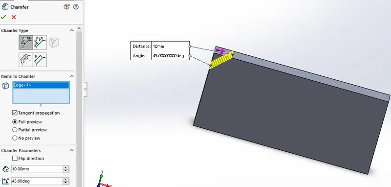
Chamfer:
The chamfer tool creates a beveled feature on
selected edges , faces , vertex .
To create a chamfer:
1. Select chamfer on features tab
2. Give parameters like which type of chamfer
(angle-distance or distance-distance)and all.
3. Click ok.
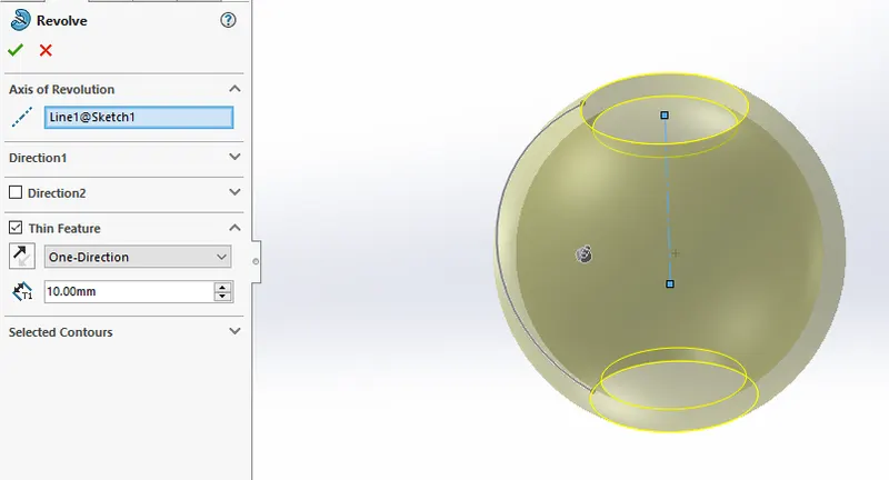
Revolve boss:
Revolves add or remove material by revolving one
or more profiles around a centerline. You can
create revolved boss/bases, revolved cuts, or
revolved surfaces. The revolve feature can be a
solid, a thin feature, or a surface. To create revolve
boss extrude draw a 2d sketch using sketch tools
and then exit the sketch and select the revolve boss
in feature tab and then select the revolve axis and
give parameters and say ok. Example :
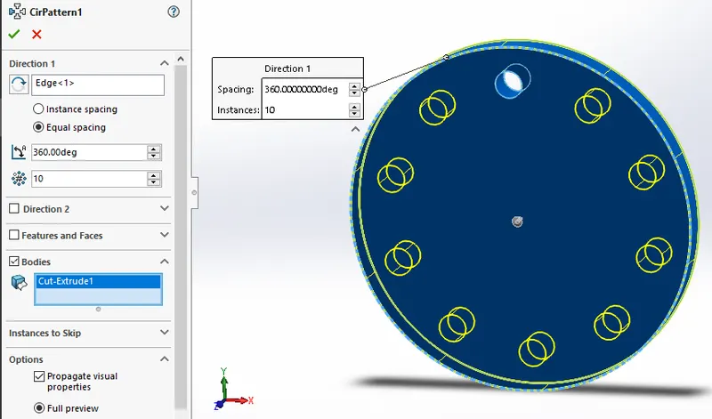
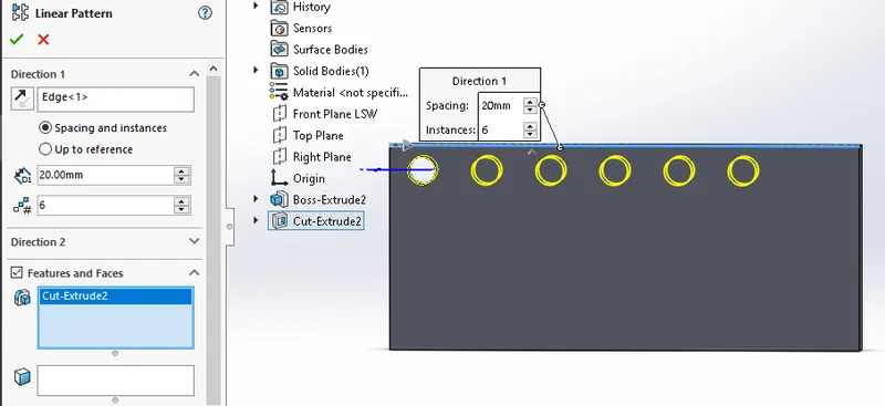
Patterns:
Pattern repeats the selected features in an array
based on a seed feature. You can create a linear
pattern, a circular pattern, a curve driven pattern, a
fill pattern, or use sketch points or table
coordinates to create the pattern.
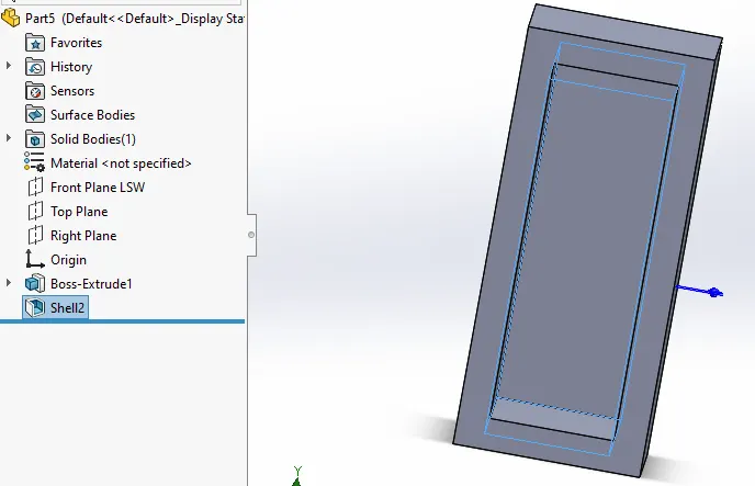
Shell:
It is very handy tool in SOLIDWORKS . It gives
some sort of idea that how inside geometry of a
part will appear . In this tool we give inside
thickness to the geometry and material removed
from the body and it becomes hollow.
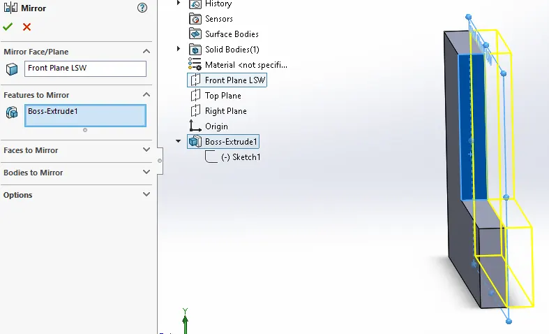
Mirror:
Mirror copies the selected features or all features,
mirroring them about the selected plane or face.
When this feature is applied it need plane or axis
to mirror . Select the body which is to be mirror ,
select an axis or plane then apply feature and the
mirrored part will get .
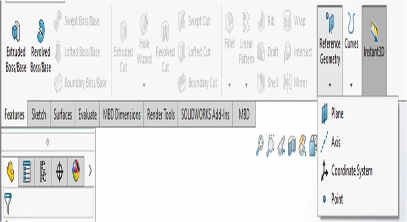
Reference geometry:
Reference geometry defines the shape or form of a
surface or a solid. Reference geometry includes items
such as planes, axes, coordinate systems, and points .
You can use reference geometry in the creation of
several kinds of features.
For example :
Planes are used in lofts and sweeps.
An axis is used in a circular pattern.
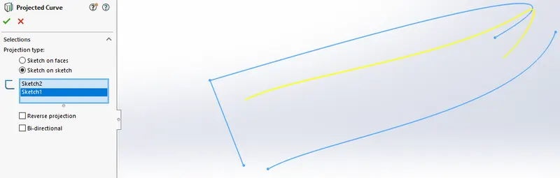
Projected curve:
You can project a sketched curve onto a model face
to create a 3D curve. You can also create a 3D
curve that represents the intersection of two
extruded surfaces generated by creating sketches
on two intersecting planes.
You can create multiple closed or open-contour
projected curves from a single sketch. You can also
use 3D sketches as input for the Projected
Curve tool.
Knit:
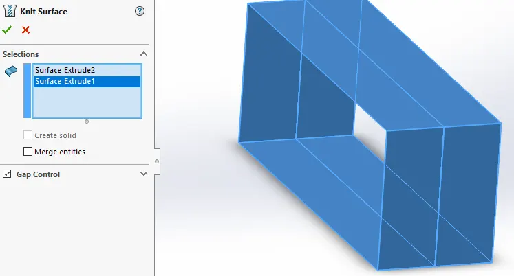
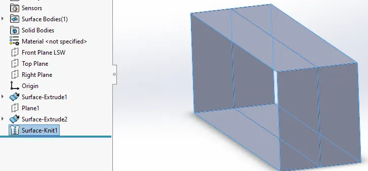
Use of knit surface tool to combine two or more
faces and surfaces into one . It creates a solid body
when the knit surfaces form a closed volume or
leaves as a surface body.
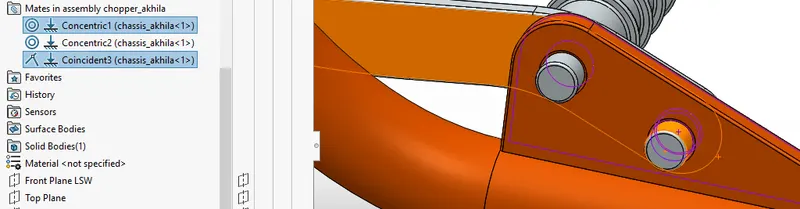
Mate:
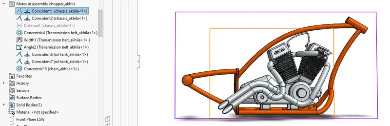
Mates create geometric relationships, such as
coincident , perpendicular , tangent , and so on
between assembly components. As you add mates,
you define the allowable directions of linear or
rotational motion of the components. You can
move a component within its degrees of freedom,
visualizing the assembly's behavior.
Sketch:
When you open a new part document, first you
create a sketch. The sketch is the basis for a 3D
model. You can create a sketch on any of the default
planes (Front Plane, Top Plane, and Right Plane), or
a created plane.
You can start by selecting :
1.Sketch entity tools (line, circle, and so on)
2. Sketch tool (entities etc…)
3. Planes
4. Extruded Boss/Base or Revolved Boss/Base on
the Features toolbar.
5.You can also create a sketch on a flat surface, a
spline on a surface, or the face of a solid.
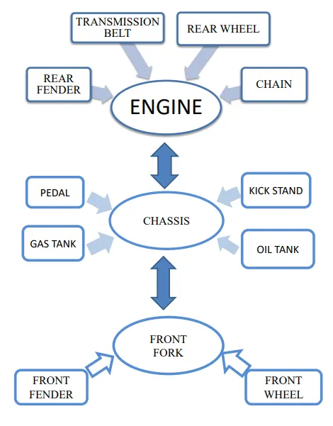
Now we completed discussion of how the features
work under SOLIDWORKS . let us see the
application of the features in the chopper that we
have built. We are going to discuss part by part as
shown in the flowchart.
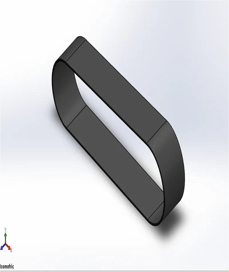
Transmission belt:
Transmission belt is located at the round surface of
the pulleys. To transmit the power with help of
pulleys. The commonly used material for this is
rubber. It is a solid body in which transmission belt
are filleted and the appearance given is matter
rubber.
Features used to create the transmission belt:
•Sketch
•Extrude
•Offset
•Fillet
•Appearance
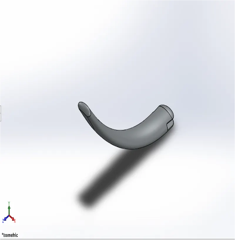
Kickstand:
While designing kickstand first we have created
sketch based on an additional plane , the part created
by using loft feature and dome has been applied on
the both sides of kickstand. Then at the bottom part
to rest the kickstand , the flat surface has created by
using sketch . We have used extruded cut for an
assembly purpose. After the part has been created
we applied fillets to the edges and at the joints of the
part. Chrome material is applied to the kickstand.
Features used to create the kickstand:
•Sketch
•Ellipse
•Splines
•Pierce
•Loft
•Cut extrude
•Boss extrude
•Split
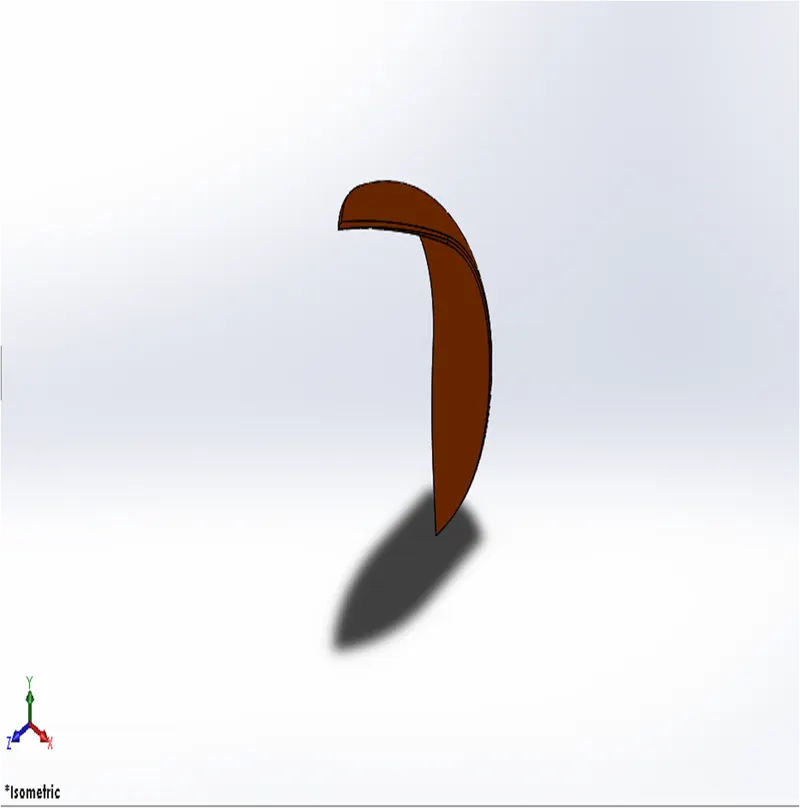
Front fender:
Here we revolved the sketch using an axis and
created half curved solid body. Some sharp edges
designed on the both sides of fender by using the
split tool the material is removed. The edges of the
fender are filleted.
Features used to create the front fender:
•Sketch
•3-point arc
•Offset
•Extend
•Trim
•Revolve
•Spline
•Fillet
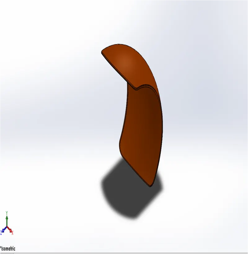
Rear fender:
Same procedure is used to make rear fender as it was
used in front fender. Only the difference between the
two are sizes as according to the size of the tire . the
front and rear fender are made of metal and
appearance given is sienna color which is bright
orange texture.
Features used to create the rear fender:
•Sketch
•3-point arc
•Extend
•Trim
•Revolve
•Spline
•Fillet
•Shell
Oil tank:
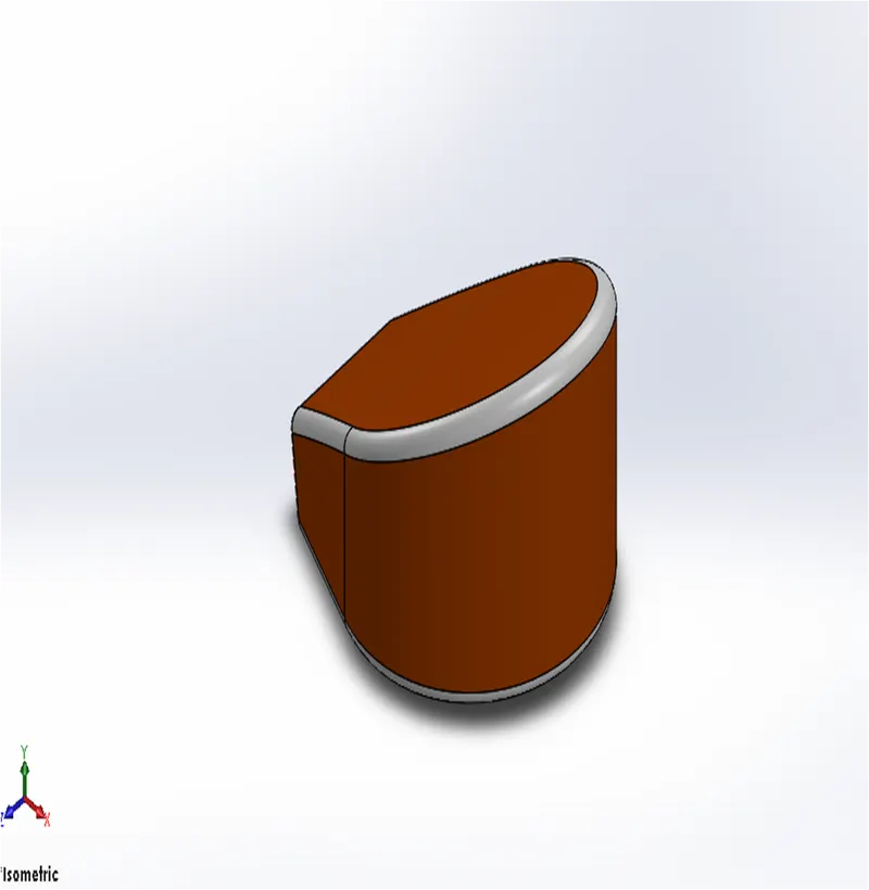
The base of the oil tank is sketched on the top
plane and extruded above to attain the structure
of oil tank and another sketch is added on the
midplane it is then extruded and then combined
together and at the end a shell function is used to
make part hollow from inside. Fillet is applied on
the outer edges to make it round. The appearance
given to the oil tank is sienna color and the edges
filleted are given white paint.
Features used to create the oil tank:
•Lines
•3-point arc
•Boss extrude
•Combine
•Fillet
•Shell
Chain:
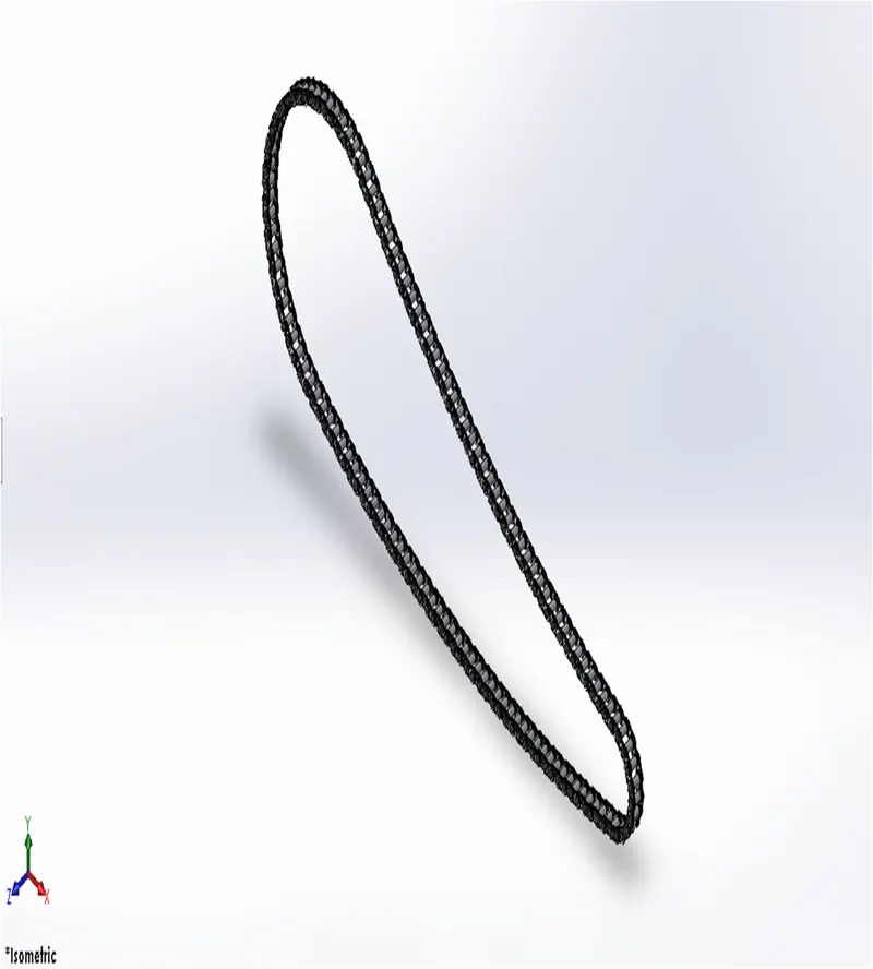
To create chain first we need to draw the sketch
using arcs and lines , the line must be tangent to
the arc . Then we draw the sketch of blocks and
pins and extrude it, then the pins and blocks were
pattern along the path and by calculating the
number of pins and blocks. When the whole front
side chain pattern created. Then front side of
blocks can be mirror to the midplane and both
side of blocks has been created. This arrangement
has been made according to the sketch. A fine
finished chrome metal is used as the appearance
of the linked chain.
Features used to create chain:
•Sketch
•Circles
•3-pint arc
•Slot
•Block
•Fillet
•Curve pattern
•Mirror
Pedal:
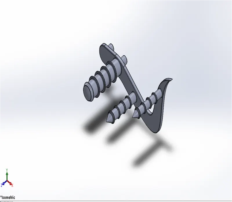
A pedal is a strong rigid body and used to rest the
front while riding bike.
Features used to create the Pedal:
• Sketch
• Lines
• Circles
• Fillet
• Revolve
• Dome
• Chamfer
• Linear pattern
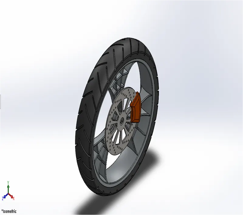
Front Wheel:
Front wheel is having larger diameter than the rear wheel.
To manage impact better than the rear. Front wheel
experiences greatest force during braking. First, the rim
was created by revolve boss feature and the spider webbed
spokes were created by using splines and offsetting them.
Then the spider webbed spokes were pattern to the rim. On
rim rotor and caliper were modelled. The tire was modelled
using revolve and threads were applied. The appearance
given to the tire is matte rubber and rotor and spokes are
chrome metal and caliper is sienna color.
Features used to create the Front wheel:
•Sketch
• Lines
•3 point arc
•Sketch fillet
•Revolve
•Spline
•Extend
•Trim
•Cut extrude
•Offset
•Revolve cut
•Circular pattern
•Chamfer
•Fillet
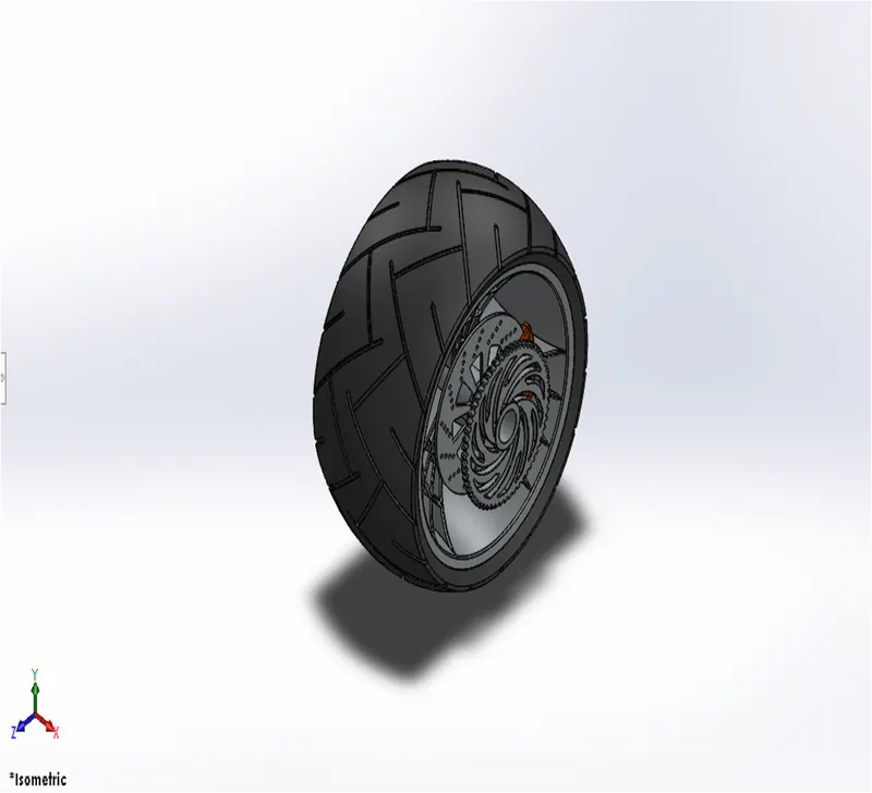
Rear Wheel:
The rear tire is primarily used for accelerating the vehicle
and move it forward. It is wider than the front wheel. It
gives stability to the vehicle. The steps were followed
same like front wheel and appearance given is also 2 same
only the component added here sprocket to link the chain.
Features used to create the Rear wheel:
•Sketch
•Lines
•3-point arc
•Sketch fillet
•Revolve
•Spline
•Extend
•Trim
• Extrude cut
• Offset
•Revolve cut
•Circular pattern
•Chamfer
•fillet
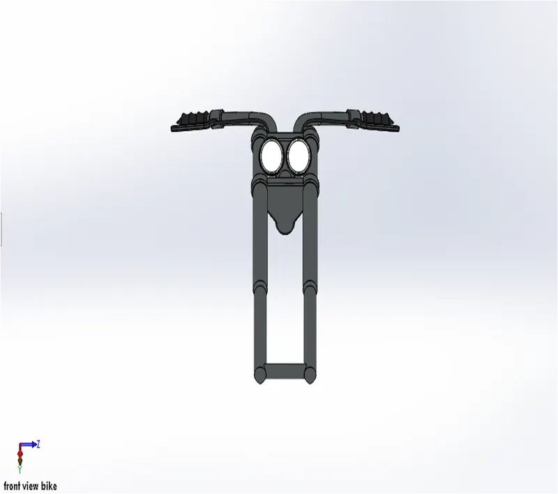
Front fork:
Front fork attach the whole chassis and the front wheel.
It is typically made with triple clamps. It is also used to
give suspension to the whole bike and front wheel
includes parts front fork, handle bars, head lights, break
and clutch levers. First the half portion of the front fork
has been created and the whole body is mirrored about
the plane. Projected curves were used to model the
handles and the cables. The handles of the front fork
were given grips.
Features used to create the Front fork:
•Sketch
•Lines
•Revolve
•Circle
•Fillets
•Linear pattern
•Spline
•Extrude cut
•Dome
•Curve
•Sweep
•Plane
•Mirror
•Combine
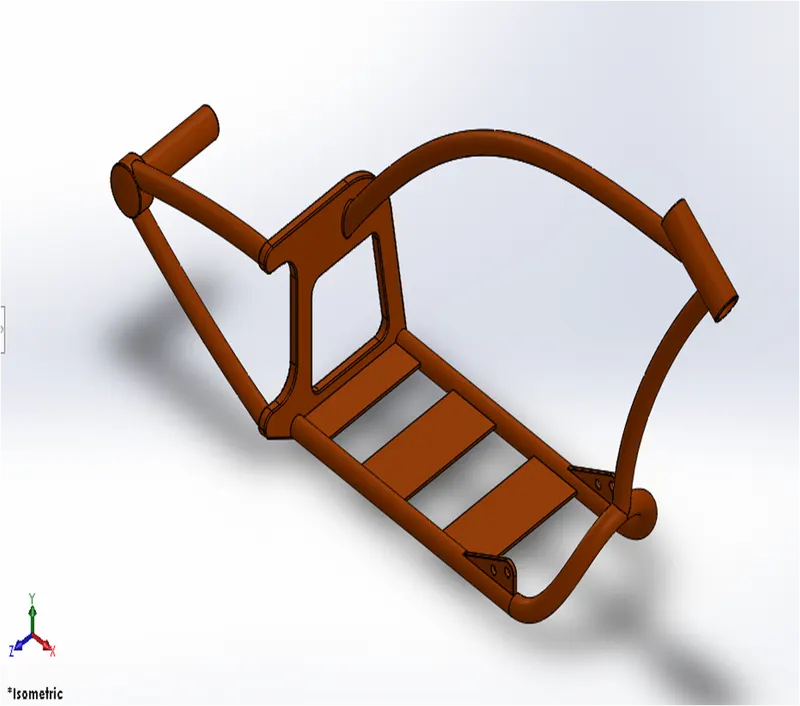
Chassis:
The chassis is the main frame of the chopper. It holds
all the components such as front fork, pedals,
kickstand, oil tank, engine, gas tank and rear wheel. It
supports all the components and supports to the bike.
The modelling of chassis starts with using chopper
image for reference. It uses features such as extruded
boss, splines, and revolving parts, making mirror and
sweep. At the end whole part created by using fillet and
it gives nice appearance to the chassis and the sharp
edges gets round. The appearance given to the chassis
is sienna color i.e. bright orange color.
Features used to create the Chassis:
•Blueprint sketch
•Splines
•Curves
•Mirror
•Boss extrude
•Extrude cut
•Chamfer
•Dome
•Split
•Revolve
•Combine
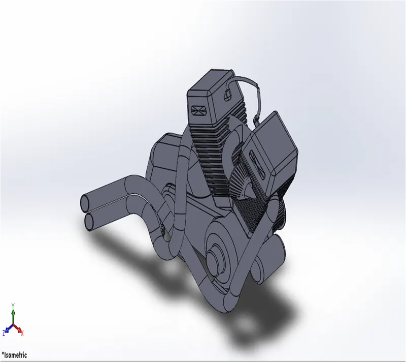
Engine:
The main part of the bike is engine. It is also called as heart
of the bike. It provides necessary power to drive the bike. A
picture is taken for the reference for modelling. The engine
consists of parts like crank shaft, transmission pulleys and
motor. The upper part of crank shaft the cooling fins 2 were
located. The air filters were drawn using spline and the
exhaust system is also made with splines and projected
curves and sweep feature. The edges of the engine were
filleted and the appearance given is chrome metal.
Features used to create the Engine:
•Sketch
•Blueprint sketch
•Lines
•Circles
•Boss extrude
•Fillet
•Revolve
•Dome
•Circular pattern
•Chamfer
•Linear pattern
•Mirror
• Cut extrude
•Combine
• Mirror
•Curve
• Composite curve
• Split
Gas Tank:
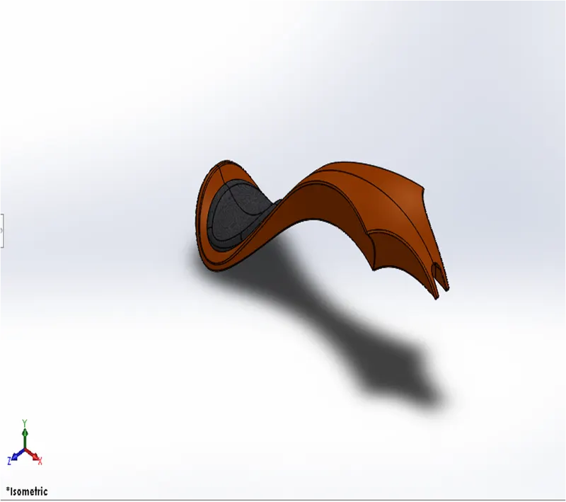
This part is mainly made with splines and sweep feature.
The half part of the gas tank first created and then it is then
mirrored about the plane. The two separated parts were
made single part by using knit feature. The gas tank covers
the oil tank and engine, and also it acts shield to prevent the
heat from the engine. The seat was modelled on the top of
the gas tank. The fillets were added to the edges of the gas
tank. At the last shell feature were added to make it hollow
from inside.
Features used to create the Gas tank:
•Blueprint sketch
•Spline
•Surface sweep
•Surface trim
•Surface boundary
•Surface loft
•Curve
•Mirror
•Surface knit
• Surface extrudes
•Fillet
•Extrude cut
•Shell
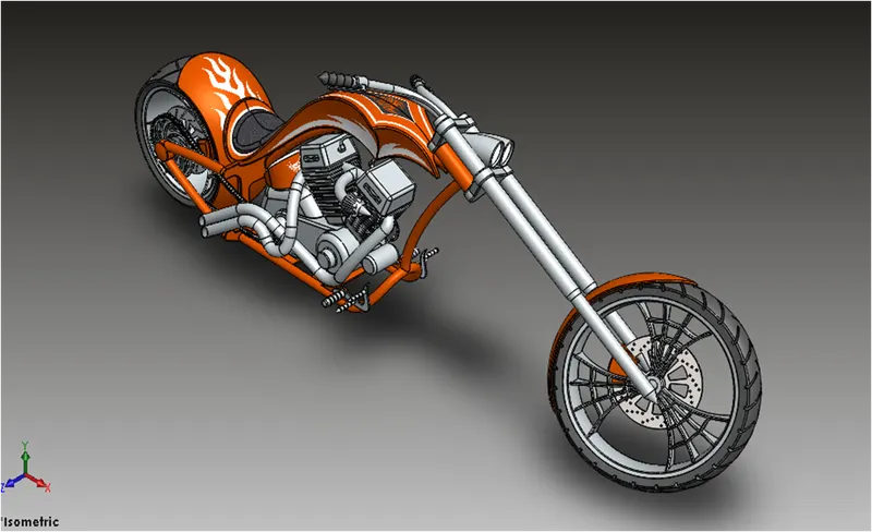
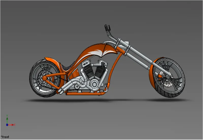
Assembly of chopper:
All the parts were modelled and were imported to assemble
them. In assembly mate 2 feature is most commonly used to
locate and relate the parts with one another. Chassis is main
component which is inserted first and then fixed. The other
components were inserted one by one and by using planes
for reference and giving the mate feature once the part gets
fixed it floats with the main frame. Some parts were
modified during assembly to make it perfect according to
requirement.
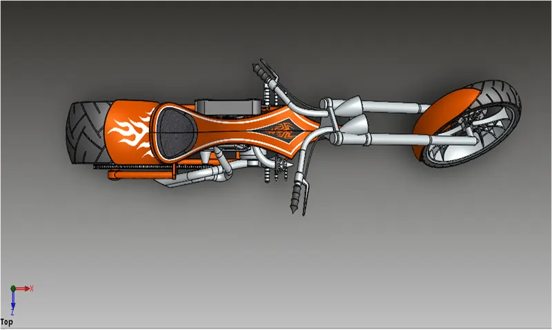
Decals:
A decal is something called a “transfer”, and it consists of a
picture, image, pattern, or design that’s printed on metal
body. We have added decals on Gas tank, Rear fender and
Oil tank of chopper. It gives nice appearance to the chopper
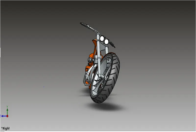
Rendering:
The term rendering comes from the graphic
world where a rendering is an artistic drawing
of what a new structure would look like. In
Computer Aided Design (CAD), a rendering
is a particular view of a realistic image. By
doing rendering of chopper we get the idea
that how it will look into the environment. This rendering is done in the SOLIDWORK
Visualize software. By using PHOTOVIEW
360 2 we can add various camera views to the
model, we can set various angles, direction,
and can set appropriate distance to get the
perfect camera view. In rendering we change
color of chopper parts, background images,
brightness, rotation and various setting of
chopper. Including the resolution and setting
number of passes we get more detail visual’s
of chopper